1 Introduction Industrial control has moved from stand-alone control to centralized monitoring and distributed control. Now it has entered the era of network-intensive manufacturing. Industrial controller networking also facilitates network management. Modbus is one of the industrial controller's network protocols. The Modbus protocol is a communication protocol applied to electronic controllers. Through this protocol, controllers can communicate with each other, controllers via a network (such as Ethernet), and other devices. It has become one of the mainstream industry standards. The control equipment he produces for different vendors that conform to the Modbus protocol can be connected to an industrial network for centralized monitoring.
2 Application Principle of Modbus RTU Protocol in GForce-200
2.1 Relationship Between Modbus RTU Protocol and GForce-200 Introduction The port 0 on the GForce-200 CPU supports Modbus RTU protocol and becomes a Modbus RTU slave. This function is implemented through the free port communication mode of the GForce-200, so it can be transmitted via wireless data radio and other slow communication devices.
If you want to use the Modbus RTU protocol for communication between the GForce-200 CPU and other devices that support Modbus RTU, you need to have a GForce-200 CPU as the Modbus master. The GForce-200 CPU as the master station must be programmed by the user in a free port mode according to the relevant protocol.
In the GForce-200 control system application, the Modbus RTU slave command library only supports communication port 0 (Port 0) on the CPU. To implement Modbus RTU communication, Step7-Micro/WIN32 V3.2 or higher programming software is required, and Step7-Micro/WIN32 V3.2 Instruction Library must be installed. The Modbus RTU function is implemented through a preprogrammed program function block in the instruction library.
2.2 Basic Procedure for Application of Modbus RTU Protocol in GForce-200 (1) First check the software version of Micro/WIN used in GForce-200 control system. It should be Step7-Micro/WIN V3.2 or later.
(2) Check whether there is Modbus RTU slave command library in the Micro/WIN instruction tree (Figure 1). The library should include two subroutines, MBUS_INIT and MBUS_SLAVE. If not, the Micro/WIN32 V3.2 Instruction Library package must be installed as shown in Figure 1.
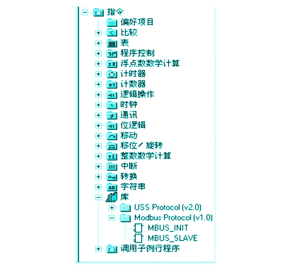
Figure 1 Library instructions in the instruction tree
(3) When programming, use SM0.1—call the subroutine MBUS_INIT to initialize, use SM0.0—call to study MBUS_SLAVE, and specify the corresponding parameters. A detailed description of the parameters can be found in the subprogram's local variables table. See Figure 2 for an example:
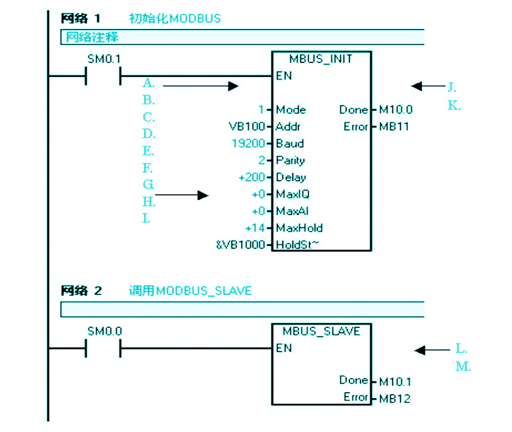
Figure 2 Calling the MODBUS Communication Library
The meaning of the parameters in Figure 2 is as follows:
â— Mode selection: start/stop MODBUS, 1=start; 0=stop;
â— Slave address: MODBUS slave address, value 1~247;
â— Baud rate: optional 1200,2400,4800,9600,19200,38400,57600;
â— Parity check: 0=no check; 1=odd check; 2=even check;
â— Delay: delay between additional characters, the default value is 0;
â— Maximum I/Q bit: The maximum number of I/O points involved in communication. The GForce-200 I/O image area is 128/128. The default value is 128.
â— Maximum number of AI words: The maximum number of AI channels that can participate in communication, which can be 16 or 32.
â— Maximum holding register area: V memory words (VW) involved in communication;
Keep register area starting address: specified with &VBx (indirect addressing mode);
â— Initialization completion flag: set to 1 after successful initialization;
â— Error code: 0=No error.
(4) Note that the call to the Step7-Mciro/WIN32 V3.2 Instruction Library requires the library command memory area to be allocated. The library instruction data area is the variable storage space used by subroutines and interrupt programs of the corresponding library. If you do not allocate the library instruction data area during programming, many of the same errors will occur at compile time.
The holding register area specified by the subroutine parameters HoldStart and MaxHold is allocated in the V data storage area of ​​the GForce-200 CPU. This data area cannot have any overlap with the library instruction data area. Otherwise, an error will occur during the operation and communication will not be possible. . Note that the holding register area in Modbus is addressed by "word", that is, MaxHold specifies the number of VW instead of VB.
3 Modbus RTU Protocol Test After compiling and downloading the project of the Modbus RTU slave instruction library to the CPU, run some Modbus test software on the programming computer (PG/PC) to check whether the GForce-200 Modbus RTU communication is normal. Finding fault points is useful. The test software connects to the CPU via a computer serial (RS-232) and PC/PPI cable. (take ModScan32 test software as an example for testing)
3.1 Test Software
Test software ModScan32 shown in Figure 3.
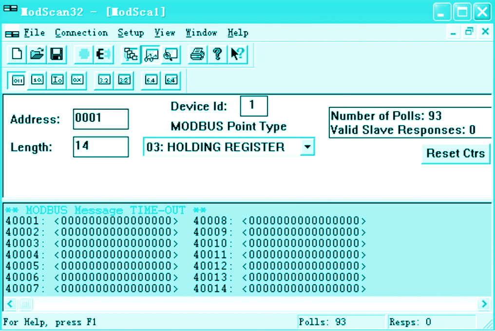
Figure 3 Modbus RTU test software: ModScan32
In Figure 3, the relevant parameters in the screen of the ModScan32 test software are as follows:
Address: the starting address of the memory area in ModBus;
Device Id: Port address of PLC ModBus;
Length: The length of the V memory word that is participating in the communication.
3.2 Parameter Setting Set the communication parameters of the ModScan32 test software to be consistent with the parameters set in the MBUS_INIT of the Modbus RTU command library of the GForce-200 so that communication detection can be performed. ModScan32 communication parameter settings shown in Figure 4.
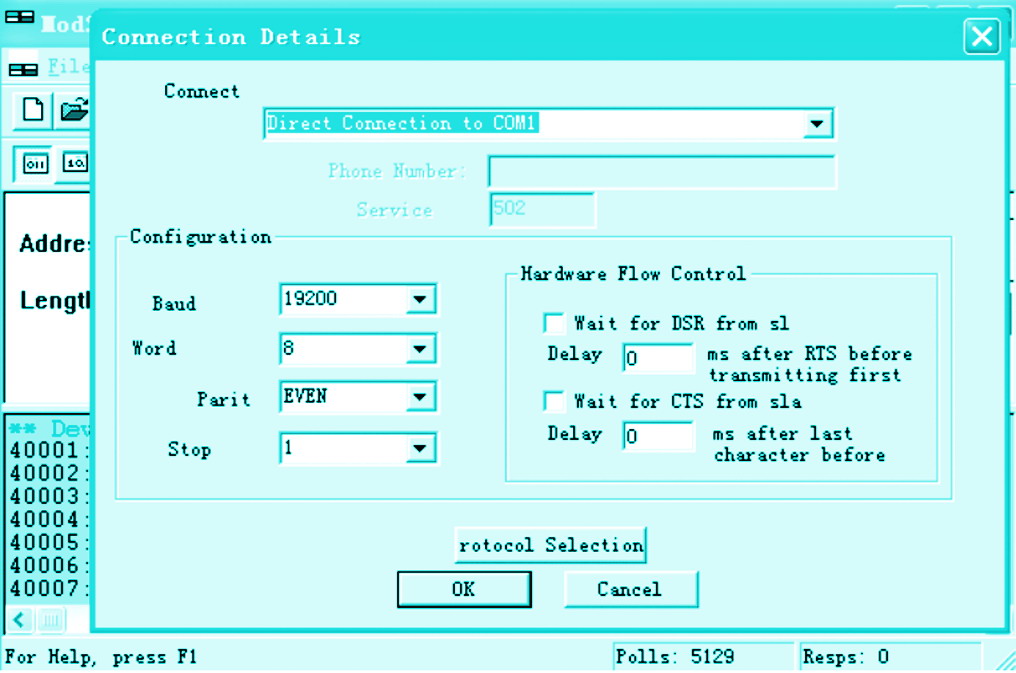
Figure 4 ModScan32 communication parameter settings
4 MODBUS RTU address and GForce-200 address correspondence MODBUS address always appears in the form of 00001, 30004 and the like. The corresponding relationship between GForce-200's internal data storage area and MODBUS's 0, 1, 3, and 4 total of 4 types of addresses is shown in the attached table:
Schedule MODBUS address correspondence table
Description: where T is the buffer start address in the GForce-200, which is HoldStart.
If you know the V memory address in the GForce-200, the formula to calculate the MODBUS address is as follows: MODBUS address=40000+(T/2+1)
Where T is an even number.
5 Conclusion Modbus RTU, as a network communication protocol for industrial controllers, plays a major role in networking, monitoring, and communication between many controllers. This article uses a typical GForce-200 control system as an example. Details how to use Modbus RTU communication protocol and detection methods to make the communication between controllers easier and clearer.