1. Introduction In this chapter, we will focus on how to use the GForce-200 PLC CPU222 for PID loop control.
2. PID Control Overview GForce-200 series PLCs are capable of PID control, and their CPUs can support up to 8 PID control loops. PID is the proportional-integral-derivative control algorithm in the closed-loop control system. It can be regarded as the sum of these three items. According to the difference between the set value and the actual value of the controlled object, the control output is calculated according to the PID method to make the feedback. Following the setpoint change, the PID control is a negative feedback closed-loop control. The proportional term is the product of the gain (Kc) and the deviation, the integral term is proportional to the sum of the deviations, and the derivative term is proportional to the variation of the deviation.
The PID control function is implemented by the PID instruction function block. In the S7-200, the PID loop instruction uses the input information and configuration information in the loop table to perform PID operations, exchange data, and programming. This instruction affects the special memory flag SM1.1 (overflow). PID operation can only be performed when the logical stack top value is 1. This instruction has two operands: TBL and LOOP (shown below). TBL is the start address of the loop table, the operand is limited to VB zone, the data type is BYTE type, LOOP is the loop number can be integer from 0 to 7, so up to 8 PID instructions can be used in the program. If two or more PID instructions use the same loop number, even if the loop tables of these instructions are different, unpredictable results may occur between these PID operations. Before using the PID instruction function block directly, all real numbers such as gain (Kc), sampling time (Ts), integral time (Ti), and derivative time (Td) must be converted into real numbers between 0.0-1.0 for PID. The instruction function block accepts, that is to say converts the actual physical quantity of the outside world into data that can be received by the PID instruction, that is, input/output conversion and normalization processing.
3. PID control programming and debugging In this set of systems, in order to meet production requirements, the boiler steam pressure should be maintained between 0.85-1.0MPa, the pressure of the size of the pressure transmitter detection, the transmitter pressure range 0-2.5MPa, DC4-20mA output. Therefore, at 0.85 MPa, the corresponding current output is 9.44 Ma, and at the same 1.0 MPa, the output is 10.4 mA. The normalized scale values ​​are shown in the figure below.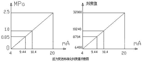
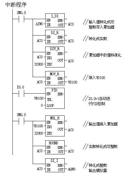
The process variable value is the unipolar analog quantity detected by the pressure transmitter and the loop output value is also a unipolar analog quantity used to control the blower speed. The range of these two analogs is 0.0 -1.0 with a resolution of 1/32000 (normalized). It can be preliminarily determined that Kc = 0.06, Ts = 0.2, and Ti = 10.0. There is no differential effect here. The program is edited as shown below.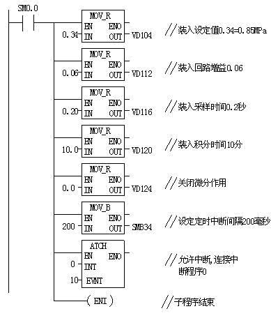
The program uses the main program, subroutines, interrupt program structure mode, the program is clear, clear, greatly reducing the cycle scan time.
4. The debugging program selects the parameters of the PID and the cooperation with each other, which can affect the stability of the PID control. If the sampling time is too short, the change of the external signal may not be detected, and an excessively long sampling time obviously cannot meet the requirement of control accuracy. Another example is that too much gain can cause control shocks. When debugging the program, pay attention to the setting of these parameters, and slowly debug until a stable PID control is achieved.
5. Conclusion PID control plays an important role in closed-loop control. Here only the speed of the blower is controlled to keep the steam pressure in the boiler constant. The PID control is introduced. Similarly, the maintenance of the negative pressure in the boiler is similar to this and is not described here in detail.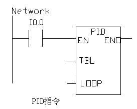
2. PID Control Overview GForce-200 series PLCs are capable of PID control, and their CPUs can support up to 8 PID control loops. PID is the proportional-integral-derivative control algorithm in the closed-loop control system. It can be regarded as the sum of these three items. According to the difference between the set value and the actual value of the controlled object, the control output is calculated according to the PID method to make the feedback. Following the setpoint change, the PID control is a negative feedback closed-loop control. The proportional term is the product of the gain (Kc) and the deviation, the integral term is proportional to the sum of the deviations, and the derivative term is proportional to the variation of the deviation.
The PID control function is implemented by the PID instruction function block. In the S7-200, the PID loop instruction uses the input information and configuration information in the loop table to perform PID operations, exchange data, and programming. This instruction affects the special memory flag SM1.1 (overflow). PID operation can only be performed when the logical stack top value is 1. This instruction has two operands: TBL and LOOP (shown below). TBL is the start address of the loop table, the operand is limited to VB zone, the data type is BYTE type, LOOP is the loop number can be integer from 0 to 7, so up to 8 PID instructions can be used in the program. If two or more PID instructions use the same loop number, even if the loop tables of these instructions are different, unpredictable results may occur between these PID operations. Before using the PID instruction function block directly, all real numbers such as gain (Kc), sampling time (Ts), integral time (Ti), and derivative time (Td) must be converted into real numbers between 0.0-1.0 for PID. The instruction function block accepts, that is to say converts the actual physical quantity of the outside world into data that can be received by the PID instruction, that is, input/output conversion and normalization processing.
3. PID control programming and debugging In this set of systems, in order to meet production requirements, the boiler steam pressure should be maintained between 0.85-1.0MPa, the pressure of the size of the pressure transmitter detection, the transmitter pressure range 0-2.5MPa, DC4-20mA output. Therefore, at 0.85 MPa, the corresponding current output is 9.44 Ma, and at the same 1.0 MPa, the output is 10.4 mA. The normalized scale values ​​are shown in the figure below.
The process variable value is the unipolar analog quantity detected by the pressure transmitter and the loop output value is also a unipolar analog quantity used to control the blower speed. The range of these two analogs is 0.0 -1.0 with a resolution of 1/32000 (normalized). It can be preliminarily determined that Kc = 0.06, Ts = 0.2, and Ti = 10.0. There is no differential effect here. The program is edited as shown below.
The program uses the main program, subroutines, interrupt program structure mode, the program is clear, clear, greatly reducing the cycle scan time.
4. The debugging program selects the parameters of the PID and the cooperation with each other, which can affect the stability of the PID control. If the sampling time is too short, the change of the external signal may not be detected, and an excessively long sampling time obviously cannot meet the requirement of control accuracy. Another example is that too much gain can cause control shocks. When debugging the program, pay attention to the setting of these parameters, and slowly debug until a stable PID control is achieved.
5. Conclusion PID control plays an important role in closed-loop control. Here only the speed of the blower is controlled to keep the steam pressure in the boiler constant. The PID control is introduced. Similarly, the maintenance of the negative pressure in the boiler is similar to this and is not described here in detail.