Keywords: DRF1601, ZigBee wireless data transmission module, ZigBee module, ZigBee protocol, industrial control, monitoring At present, more and more industrial sites may need to quickly establish a monitoring network, due to the limitations of the wiring, the use of wireless networks is a good choice ZigBee protocol has the advantages of convenient networking, strong network self-repair capability, multiple support nodes, low power consumption, etc. It is increasingly becoming an important networking method.
DRF1601 is a good ZigBee wireless data transmission module. It is produced by Shenzhen Dingtech Electronics Co., Ltd. It converts RS232 data into ZigBee data and sends it to the corresponding nodes. The use of DRF1601 completely eliminates the need to understand ZigBee protocol. All modules After the power is turned on, the network can be automatically established. If the user inputs the target address + data to the serial port, the corresponding data can be sent to the target address.
The ZigBee network has three different types of nodes: Coordinator, Router, and End Device. By programming different application codes, the DRF1601 can be configured as the above three nodes. DRF1601 reserves Debug interface, which can easily change the node type.
First, DRF1601 structure DRF1601 with a DB9 RS232 serial port, can send and receive data through the serial port, the default baud rate is 384000bps.
The supply voltage is DC 5-9V.
The main chip is TI CC2530F256, TI's second-generation ZigBee SOC chip.
Two buttons: TEST, when pressed, can send a test data to Coordinator, can observe ZigBee network structure through TI Sensor Monitor software; RESET, reset key, when revising module PAN ID, press reset key to come Restart the module.
Whip 2.4GHz antenna, the effective use of the distance is 400 meters (visible without shielding distance).
Second, DRF1601 fast networking Using TI's Sensor Monitor software, you can easily see the structure of the entire ZigBee network, this software can be downloaded from the TI's website:
1. Connect the Coordinator module to the host (such as a PC) through RS232 and power it on. Start the TI Sensor Monitor software.
2. Select the correct COM port in TI Sensor Monitor and click RUN to run the software.
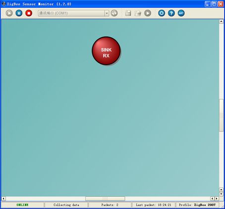
3. If the Coordinator module is properly connected, the Coordinator node will turn red;
5. Power on the other End Device modules that need to be added, and press the TEST button. You can see that the End Device module has joined the network.
6. At this point, the entire ZigBee network is established and data can be transferred between any nodes.
The process of establishing a network is as follows:
Connect Coordinator module to PC and run TI SensorMonitor
Selecting the correct COM port After running TI Sensor Monitor, the Coordinator node will power up Red End Device and press the TEST button to see the End Device join the network. 3. The data transmission structure of the DRF1601 is very easy to use. One data transmission is required. The command format is as follows:
Data Transfer Command (0xFD) + Data Length + Destination Address + Data (Up to 32 Bytes by default, up to 256 Bytes can be adjusted depending on the application)
If you want to achieve the following data transmission tasks:
Data is transmitted from the 0x7973 node to the 0x1431 node. The data format is:
0xFD 0x0A 0x31 0x14 0x01 0x02 0x03 0x04 0x05 0x06 0x07 0x08 0x09 0x10
0xFD: Data Transfer Instruction 0x0A: Data Length (Data Length of Data Area)
0x31 0x14: destination address, low first, combined together 0x1431
0x01 0x02 0x03 0x04 0x05 0x06 0x07 0x08 0x09 0x10: The data received 0x1431 is:
0xFD 0x0A 0x31 0x14 0x01 0x02 0x03 0x04 0x05 0x06 0x07 0x08 0x09 0x10
That is, receive data = transmit data If you want to send data to the Coordinator, simply change the destination address to 0x0000.
Fourth, DRF1601's setting Through DRF1601's serial port, you can easily do some basic settings for the module:
(1) Set the PAN ID of the module to a specific value (eg 0x1968)
0xFC Data Length (1 Bytes) Command Format (91 01: Write PAN ID) PAN ID Value (Lowest First)
FC 02 91 01 68 19 (restart must take effect, press RESET)
(2) Set the PAN ID of the module to the default value (0x199B)
0xFC Data Length (1 Bytes) Command Format (91 02: Write PAN ID)
FC 00 91 02 (restart must take effect, press RESET)
(3) Read the PAN ID of the module
0xFC Data Length (1 Bytes) Command Format (91 03 : Read PAN ID)
FC 00 91 03
Return: 9B 19 (The PAN ID of the module is 0x199B)
(4) Read the address of the module (Short Address)
0xFC Data Length (1 Bytes) Command Format (91 04: Read Short Address)
FC 00 91 04
Returns: 6F 79 (The module's Short Address is 0x796F)