First, the master-slave mode of 51 single-chip microcomputer, first set the working mode 3: (master-slave mode + variable baud rate)
SCON serial port function register: SM0=1; SM1=1 (working mode 3) 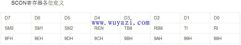
Note: Both the master and slave must work in mode 3.
[Working mode 2 (SM0 SM1 : 1 0): The serial port is an 11-bit asynchronous communication interface. The transmission or reception of one frame of information includes a 1-bit start bit "0", an 8-bit data bit, a 1-bit programmable bit, and a 1-bit stop bit "1". Send data: Before sending, the software sets TB8 to “parity bit†or “data flag†according to the communication protocol, and then writes the data to be sent to SBUF, which can start the transmitter. The transmission process is initiated by executing any instruction that uses SBUF as the destination register. The 8-bit data is loaded into SBUF, and TB8 is also loaded into the 9th bit of the transmit shift register, and then from TXD (P3.1). The port outputs one frame of data. Receive data: REN=1 first, so that the serial port is allowed to receive, and RI must be cleared to “0â€. Then according to the state of SM2 and the state of the received RB8, it is determined whether the serial port sets R1=1 after the information arrives, and requests an interrupt to notify the CPU to receive the data. When SM2=0, regardless of whether RB8 is "0" or "1", RI=1 is set, and the serial port will receive the transmitted information. When SM2=1, and RB8=1, it means that in the case of multi-machine communication, the received information is “address frameâ€. At this time, RI=1, the serial port will receive the sent address. When SM2=1, and RB8=0, it means that in the case of multi-machine communication, the received information is “data frameâ€, but it is not sent to the slave. At this time, RI is not set to “1â€, so the receiver receives in SBUF. The data frame will be lost.
Mode 3 (SM0 SM1 : 1 1): 11-bit asynchronous communication with variable baud rate. Except for the difference in baud rate, the other methods are the same as mode 2. 】ã€The above content is taken from the network】
Second, the host configuration when sending "address", set TB8 to 1, TB8 is set to 0 when sending data
(Similar: host TB8=1 sends the address, TB8=0 sends the data)
Send frame structure: 
Suppose the host will send "1234" to the slave with address 1: Call the function: TXdata(1,"1234$");
Void TXdata(uchar addr,uchar *str)
{
TB8 = 1; //send address
SBUF = addr; //send the address
While(!TI); //Determine whether the transmission is successful (TI will be set after successful transmission, and need to be cleared manually)
TI = 0;
TB8 = 0; //send data
While(*str != "\0") //Send array
{
SBUF = (*str);
While(!TI);
TI = 0;
Str++;
}
}
Third, the slave configuration
1. When receiving from the slave, first initialize the serial port, make SM2=1 (receive the address mode, that is, only receive the data of TB8=1, trigger the interrupt), the host sends the data of TB=0, which is considered to be on the bus. The communication data sent by the host to the other machine is discarded by the host without interruption.
2. After the received address matches the local address, make SM2=0 (receive data mode, receive data normally trigger interrupt)
(Similar: slave SM2=1 only receives address, SM2=0 only receives data)
Void chuan() interrupt 4 // serial interrupt service function
{
ES = 0; //turn off the serial port interrupt
If (RI) / / again judge whether the data is received (after receiving the data, RI will be set to 1, need to manually clear 0)
{
RXData = SBUF;
If (RXstart) / / determine whether this address has been received
{
If(RXData != "$") //Determine whether the data end flag is received.
{
Temp[j] = RXData; // did not receive the end flag, save the data to the array normally
j++;
}
Else // received the end flag $
{
RXstart= 0; //This reception ends
SM2 = 1; // Reconfigure to: Receive only address mode, interrupted next time TB8=1 is sent
j = 0;
}
}
If(RXData == 1) //Determine whether to call the machine, the address range: 000 – 254 (00 - FE)
{
RXstart = 1; //Start receiving data
SM2 = 0; //Configured as: Receive Data Mode
}
}
RI = 0; //Clear the receive flag
ES = 1; //Restart serial port interrupt
}
Fourth, the serial port initialization configuration
89S51, 52, STC12Cxxx + 11.0592M crystal, 9600bps
Void UART_init()
{
TMOD = 0x20; //Timer 1, working mode 2: 8 bits, auto reload
TH1 = 0xfd; //fd: 9600bps @ 11.0592M
TL1 = 0xfd; //e8: 1200bps @ 11.0592M
//f4: 2400bps @ 11.0592M
REN = 1; //Allow serial port reception
SM0 = 1;
SM1 = 1; //SM0 and SM1: Serial operation mode 3, master-slave mode + variable baud rate
SM2 = 1; //Receive only the address (the slave is configured this way, the host does not need it)
ES = 1; //Open serial port interrupt
TR1 = 1; //Start timer 1
EA = 1; //Interrupt main switch
}
Five, wiring diagram and notes 
1. Communication between the slave and the slave can only be relayed through the host.
2. The TXD output of each slave cannot be set to push-pull output, and should be set to open-drain output.
3, the communication bus can not be too long, preferably no more than 2 meters.
CS-211S: 1+1 pockets coin counter and sorter,
CS-311S: 2+1 pockets coin sorter
CS-610S+PRO: 6+1 pockets coin sorter
CS-910S+: 9+1 Pockets coin sorter
Those 4 models are all with alloy sensor for counterfeit detection
CS-600B: 6+1 pockets, mainly sort coins by diameter, no counterfeit detection
Coin Sorter,Coin Sorter With Detection,Coin Sorter For Euro,Currency Sorting Machine
Suzhou Ribao Technology Co. Ltd. , https://www.ribaoeurope.com