Overview:
A typical wall adapter that plugs into a wall outlet costs about $3 a year. Through the ENERGY STAR program, many countries in North America are working to reduce this cost and reduce the pollution caused by the power supply. Many wall adapters and other low-power isolated power supplies use a reverse converter because of its simple structure and low cost. However, the inverter is not known for its high efficiency, especially at low output voltages. In those applications where efficiency is paramount, don't rush to remove the reverse converter from the alternative solution. With just a few tricks we all know, you can increase the efficiency of the reverse converter by about 10%.
In conventional diode-rectified inverting converters, the output diode rectifier is an important cause of power loss. The average current of the output diode is equal to the DC output current, and the peak current may be several times, depending on the duty cycle. Schottky diodes typically have a forward voltage drop of 0.5V, while standard PN junction diodes have a forward voltage drop of 0.8V. This large forward voltage drop results in relatively high losses in the diode, greatly reducing efficiency. Using a synchronous MOSFET instead of a diode can greatly reduce these conduction losses. Figure 1 depicts how a standard diode rectified reverse power supply is converted to a self-driven synchronous reverse power supply.
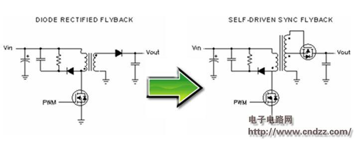
Figure 1. Self-Driven Synchronous Reverse Conversion In a self-driven synchronous reverse power supply, the output diode is replaced by an N-channel MOSFET, and a winding must be added to the power transformer to generate a synchronous gate drive signal. Compared to the output diode rectifier, the low on-resistance of the synchronous MOSFET results in lower conduction losses, which greatly increases the efficiency at high load currents.
There is a fundamental difference between the diode rectification reverse structure and the synchronous reverse structure. The key waveforms are shown in Figure 2. The diode diode rectifies the output diode of the reverse structure to prevent secondary current reflow of the transformer. In the light load state, this causes the discontinuous current mode (DCM) when the secondary current of the transformer is completely discharged to the output at the end of each cycle. The synchronous MOSFET allows current to flow continuously to the negative direction and allows the synchronous reverse structure to always operate in continuous current mode (CCM) regardless of the load current. This situation is often beneficial because the control loop gain does not drop as it goes into DCM operation, maintaining full dynamic performance (even under zero load conditions). The use of synchronous MOSFETs can have a detrimental effect on zero or light load efficiency because the relatively large AC current flows with little or no net DC output current. The transformer and primary MOSFET switching losses associated with these loop currents are greater than in the diode rectified reverse structure, and their current is reduced under light load conditions.

Figure 2 DCM and CCM operation
(Please read the PDF for details)
Dongguan Rongmao technology Co.,ltd , https://www.szroomoo.com