The probe capacitor polarity needle has a head diameter of 5.8. The total length of the 7-pin and 12-pin needles is 5.
Supply 1206 red and green two-color 1210 red and green two-color LED light-emitting diode
L0504-Murata muRata common mode inductor 90Ω 150mA
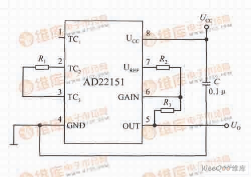
Temperature compensation circuit diagram in bipolar mode
The temperature compensation circuit in the bipolar mode formed by the AD22151 is shown in the figure. The circuit has the following characteristics: 1 connecting the temperature compensation resistor R1 between the TC2 terminal and the TC3 terminal; 2 the magnetic field zero point is biased on the UCC/2; 3 can be a low temperature coefficient below -500×10-6/°C. Make compensation.
SAA Cable Mount Connectors,SAA Bulkhead Mount Connectors,SAA Flange Mount Connectors,SAA PCB Mount Connectors
Xi'an KNT Scien-tech Co., Ltd , https://www.honorconnector.com