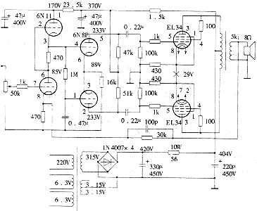
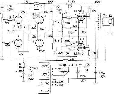
We know that the internal resistance will be greatly reduced and the linearity will be improved after changing the power pentode or beam tetrode to triode connection. Under the condition that the primary and secondary turns ratio of the output transformer is fixed, the reduction of the internal resistance of the output tube will reduce the output resistance of the amplifier. In this way, the damping of the loudspeaker will be increased, so that the movement of the paper cone will be "prohibited" and the transient distortion will be reduced. In addition, in the power amplifier, the nonlinear distortion produced by the triode is that the amplitude of the second harmonic is greater than the amplitude of the third harmonic, and the pentode or beam quadrupole is the third harmonic distortion is greater than the second harmonic distortion. According to theoretical analysis, the push-pull amplifier can eliminate even-order harmonic distortion under the condition of symmetrical circuit parameters, but it is powerless for odd-order harmonic distortion. Therefore, the use of triodes for push-pull amplification can reduce nonlinear distortion. However, after changing from pentode to triode connection, the maximum output power of the amplifier will be greatly reduced. For example, the M100KIT circuit was originally a super linear connection method, and the output power of more than 40W can be obtained under the condition of a power supply voltage of 400V. When the transistor connection method is changed, the output power will be reduced to about 16W.
EL34 is a well-known power output tube with good reputation, and it is similar to KT66. The main characteristic parameters of several common power tubes are listed in Table 1. Table 1
| model | 6P3P | FU7 | FD422 | KT66 | EL3 | KT88 | FU50 |
| Filament voltage (V) | 6.3 | 6.3 | 6.3 | 6.3 | 6.3 | 6.3 | 12.6 |
| Filament current (A) | 0.9 | 0.9 | 1.5 | 1.27 | 1.5 | 1.6 | 0.8 |
| Maximum curtain grid voltage (V) | 330 | 300 | 250 | 500 | 425 | 600 | 250 |
| Maximum curtain grid power dissipation (W) | 2.75 | 3.5 | - | 3.5 | 8 | 8 | 5 |
| Maximum screen voltage (V) | 400 | 600 | 750 | 500 | 800 | 800 | 1000 |
| Maximum screen power dissipation (W) | 20.5 | 25 | 30 | 25 | 25 | 42 | 40 |
| Maximum cathode current (mA) | - | 120 | - | 200 | 150 | 200 | 230 |
| As can be seen from Table 1, the tubes with the maximum curtain grid voltage greater than 400V include EL34, KT66, and KT88, which are more suitable for use as a triode under the condition of 400V power supply voltage. The typical working example of EL34 is shown in Table 2. Table 2 |
| Connection | Five poles | Super linear | Tripolar | |||
| Job category | Single-ended A1 | Push-pull AB1 | Push-pull AB1 | Single-ended A1 | Push-pull AB1 | |
| Power supply voltage (V) | 265 | 375 | - | - | 375 | 400 |
| Screen voltage (V) | 250 | 355 | 450 | 430 | - | - |
| Screen current (mA) | 100 | 2 × 75 | - | - | 70 | 2 × 65 |
| Curtain grid voltage (V) | 250 | - | - | - | - | - |
| Curtain grid resistance (Ω) | 0 | 470 two tubes | - | - | - | - |
| Curtain grid current (mA) | 14.9 | 2 × 11.5 | - | - | - | - |
| Gate voltage (V) | -13.5 | - | - | - | - | - |
| Cathode resistance (Ω) | - | 130 | 240 | 240 | 370 | 220 |
| Load resistance (kΩ) | 2 | 3.4 | 6 | 6 | 3 | 5 |
| Output power (W) | 11 | 35 | 40 | 34 | 6 | 16.5 |
| Non-linear distortion% | 10 | 5 | - | - | 8 | 3 |
| The working state of the last column of Table 2 is the three-pole connection push-pull amplification operation mode. When the power supply voltage is 400V, the output power of 16.5W can be obtained, and the nonlinear distortion is only 3%. At this time, the load impedance is required to be 5kΩ (P-P). The output transformer in the Opel M100KIT just meets the requirements. Although this example is AB1-type push-pull amplification, the quiescent current of the screen is large, the two tubes have a total of 130mA, the cathode resistance is 220Ω, and the upper DC voltage is 28.6V, which is used as the negative bias of the self-sufficient gate. It should be pointed out that this self-sufficient bias method can only be applied to Class A or Class A amplifier circuits close to Class A, but not to Class B or Class A amplifier circuits with small static circuits. Because in the Class B amplifier circuit, the quiescent current of the power amplifier tube is zero, it is not possible to use the cathode resistance to generate a self-sufficient bias. If the screen static current of the Class A and Class B amplifier circuit is selected to be small, the screen current will also change with the size of the input signal. When the self-sufficient bias method is adopted, the gate bias voltage will follow the average current of the screen Increase and increase, this situation will cause a decrease in output power. In the class A push-pull power amplifier circuit, the DC voltage generated on the cathode resistance of the two-tube screen static current is used as the grid bias voltage. When there is a signal input, when the current of one tube increases, the other tube The current is decreasing. Under the premise that the parameters of the push-pull circuit components are symmetrical and there is no distortion, the increased current of one tube and the decreased current of the other tube are equal. At this time, the average current flowing through the cathode resistance is unchanged, so the gate bias can be maintained The pressure does not change with the input signal. Because the AC currents of the two tubes cancel each other out in the cathode resistance, in the class A push-pull power amplifier circuit, even if there is no parallel bypass capacitor at both ends of the cathode resistance, there will be no negative feedback of AC current. The power amplifier stage of M100 and its kit uses an independent gate bias circuit. The dedicated negative voltage rectification and filter circuits provide independently adjustable gate negative voltage for the four power amplifier tubes. Each power amplifier tube uses only a 10Ω resistor. Current sampling for debugging. The advantage of this circuit method is that under the same power supply voltage, a larger output power can be obtained. The method of changing it to a triode class A push-pull amplifier is very simple. The circuit is shown in Figure 1. The specific steps are as follows:  ①①1. Reconnect the EL34 curtain grid resistor to the screen electrode, the resistance value is 100 ~ 220Ω, the purpose is to prevent self-excitation.  ② ② After the installation of the machine, a simple test was carried out. The main technical indicators are as follows: |

Follow WeChat

Download Audiophile APP

Follow the audiophile class
related suggestion