0 Introduction Among the various parameters of digital receivers, frequency is one of the most important parameters, it can reflect important functions such as the function and use of the receiver, as well as the spectrum width. Conventional sequential frequency measurement techniques typically continuously sample the frequency domain by scanning the receiver frequency band. The method is simple in principle and mature in technology. However, the contradiction between frequency interception probability and resolution is difficult to solve, and full probability signal interception cannot be achieved. The multi-channel frequency detection technology belongs to instantaneous frequency measurement, and its architecture uses multiple frequency windows (multiple channels are connected to each other) to cover the entire frequency band of the receiver, so that when the signal enters any window, the window The frequency value can be detected. Therefore, the method can solve the contradiction between frequency intercept probability and frequency resolution, and also provides a reference scheme for realizing full probability frequency capture.
1 multi-channel modelWhen a real signal is sampled by A/D and then subjected to orthogonal down-conversion processing, two phase I and Q phase quadrature signals are obtained, which form a complex signal. A schematic diagram of the channelization of the complex signal is shown in FIG.
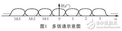
The channel shown in Figure 1 is a mutually overlapping channel that covers the frequency range of the entire zero IF signal. In general, multiple channels are often implemented using digital filter banks, but this method requires designing M (M is the number of channels) different band-pass filters with different center frequencies. This kind of structural design is too complicated, and it also increases the operation speed of subsequent signal processing, which is extremely disadvantageous for real-time processing. The low-pass implementation of the digital filter bank is to multiply each channel by a conversion factor, which is equivalent to moving the actual signal to zero IF, and then obtaining the frequency signal through the LPF. The method can perform channelization separation on the frequency band of the band-pass signal, but the new problem is that when the LPF implements M filtering operations by using the FIR filter, it will occupy a large hardware resource, and the system work efficiency is low. Currently, this structure has been replaced by a highly efficient DFT polyphase filter bank structure.
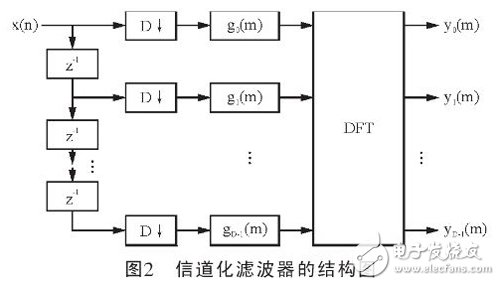
Figure 2 shows a generalized channelization efficient structure based on DFT polyphase filter bank. As can be seen from Figure 2, before filtering, D-decreasing the data can reduce the computational complexity of the filtering process. , gn(m) is the polyphase component of the low-pass prototype filter hLP(n), and its order can be reduced to the original 1/D, so the DFT can be implemented by FFT. In fact, in this structure, the complexity and data rate of the system are greatly reduced, and the real-time processing capability is improved.
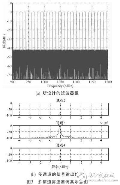
Each channel in the low-pass filter structure is formed by multiplying the prototype low-pass filter by a twiddle factor. According to requirements, Figure 3 shows the filter bank formed by the 256-stage prototype low-pass filter and its signal output simulation waveform. The effective bandwidth of this signal is 300MHz, which is divided into 32 channels, and the bandwidth per channel is 9.375MHz. If the frequency is fed to this filter bank? =28.1MHz single-frequency signal, then, through theoretical calculations, the signal should have output in channel No. 3. Figure 3 (b) shows the output simulation results of the 2nd, 3rd, and 4th channels. It can be seen that only the third channel has a relatively strong signal output, which is consistent with the theoretical calculation.
The FPGA chip selected for this design is Xilinx's Virtex-4SX55. The chip has abundant clock resources, and the arithmetic unit and dedicated memory module and configurable logic are very flexible, which is very suitable for the function realization of the current signal processing system. Therefore, according to the structure shown in FIG. 2, a channelization solution based on the DFT polyphase filter bank can be obtained, and the specific implementation structure is as shown in FIG. 4.
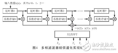
The structure shown in Figure 4 consists of a delay, a coefficient memory, a multiplier and an FFT. The delay device can implement a delay of 32 cycles for the input data, and the memory is used to store the filter coefficients. The implementation and simulation results of several main component modules in the structure are introduced below.
Screen film cutting machine provides a complete solution to solve the pressure on finished film inventory of various mobile phone accessories suppliers. It`s suitable for individual entrepreneurship or mobile phone repair stores.
The most important is that the machine can help you solve the problems of selling and applying traditional Screen Protector films.
The advantages of screen film cutting machine are keep away from inventory pressure, low investment cost, and achieve profitability, etc.
Intelligent Mini Hydrogel Machine,Hydrogel Protector Cutter Machine,Smart Protective Film Cutter,Sticker Cutting Machine
Shenzhen TUOLI Electronic Technology Co., Ltd. , https://www.hydrogelprotectors.com