The sixth chapter is to reuse the peripheral driver code. The content of this article is 6.2 SPI NOR Flash memory.
6.2 SPI NOR Flash Memory
SPI NOR Flash is a non-volatile flash memory chip with SPI interface. This section uses Taiwan's Wanghong Electronics' MX25L1606 as an example to describe how to use similar flash memory in AMetal.
>>>6.2.1 Basic functions
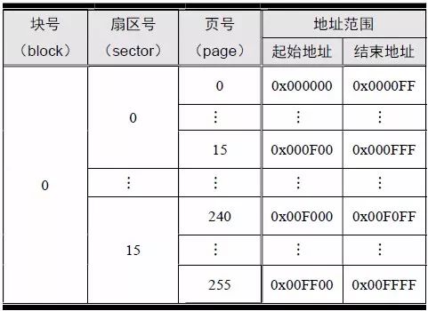
The total capacity of the MX25L1606 is 16M (16 × 1024 × 1024) bits, which is 2M bytes. Each byte corresponds to a memory address, so the address range in which it stores data is 0x000000 ~ 0x1FFFFF.
In the MX25L1606, memory has the concept of blocks, sectors, and pages. The page size is 256 bytes, each sector contains 16 pages, the sector size is 4K (4096) bytes, each block contains 16 sectors, and the block size is 64K (65536) bytes. See Table 6.5 for details.
Table 6.5 MX25L1606 Memory Organization Structure
The communication interface of the MX25L1606 is a standard 4-wire SPI interface (supports mode 0 and mode 3), namely CS, MOSI, MISO, CLK, as shown in Figure 6.3. Among them, CS (#1), SO (#2), SI (#5), SCLK (#6) are the CS, MISO, MOSI and CLK signal pins of SPI, respectively. In particular, WP (#3) is used for write protection and HOLD (#7) is used to suspend data transmission. In general, these two pins are not used and can be pulled high by a pull-up resistor. The MicroPort-NorFlash module is connected to the AM824-Core via the MicroPort interface.

Figure 6.3 SPI Flash circuit schematic
>>>6.2.2 Initialization
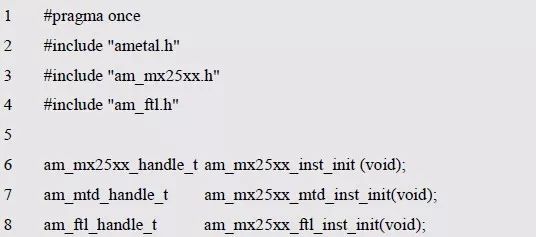
AMetal provides driver functions that support the popular SPI Flash devices such as the MX25L8006, MX25L1606, etc., and must be initialized before using other functional functions. The function prototype (am_mx25xx.h) is:
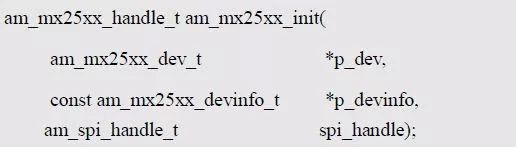
This function is intended to get the instance handle mx25xx_handle of the device. Where p_dev is a pointer to an instance of type am_mx25xx_dev_t and p_devinfo is a pointer to instance information of type am_mx25xx_devinfo_t.
(1) Example
An example of defining the am_mx25xx_dev_t type (am_mx25xx.h) is as follows:

Where g_mx25xx_dev is a user-defined instance whose address is passed as an argument to p_dev.
(2) Instance information
The example information mainly describes the specific information of the specific device, namely the SPI chip select pin used, SPI mode, SPI rate and device specific model. The definition of the type am_mx25xx_devinfo_t (am_mx25xx.h) is as follows:
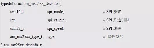
Among them, spi_mode is SPI mode, MX25L1606 supports mode 0 (AM_SPI_MODE_0) and mode 3 (AM_SPI_MODE_3). Spi_cs_pin is the chip select pin associated with the actual circuit. When the MicroPort-NorFlash module is connected to the AM824-Core through the MicroPort interface, the default chip select pin is PIO0_1. Spi_speed is the frequency of the clock signal. For the MX25L1606, the maximum supported frequency is 86MHz, so you can set this value directly to 86000000. However, since the LPC824 chip has a main frequency of 30MHz, the SPI maximum rate is only 30MHz. Type is the model number of the specific device, which contains information about the specific model, such as page size information. For the currently supported device models, see the corresponding macro in am_mx25xx.h. The macro corresponding to MX25L1606 is AM_MX25XX_MX25L1606.
Based on the above information, the instance information is defined as follows:
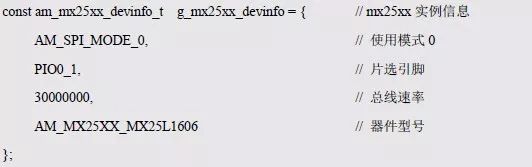
Where g_mx25xx_devinfo is user-defined instance information whose address is passed as an argument to p_devinfo.
(3) SPI handle spi_handle
If SPI0 of the LPC824 is used to communicate with the MX25L1606, the SPI handle is obtained by the SPI0 instance initialization function am_lpc82x_spi0_inst_init() of the LPC82x. which is:

The SPI handle can be passed directly as an argument to spi_handle.
(4) Example handle
MX25L1606 Initialization function am_mx25xx_init () return value MX25L1606 instance handle, as the argument of the first parameter (handle) of other function interfaces (erase, read, write).
Its type am_mx25xx_handle_t(am_mx25xx.h) is defined as follows:

If the return value is NULL, the initialization fails; if the return value is not NULL, the valid handle is returned.
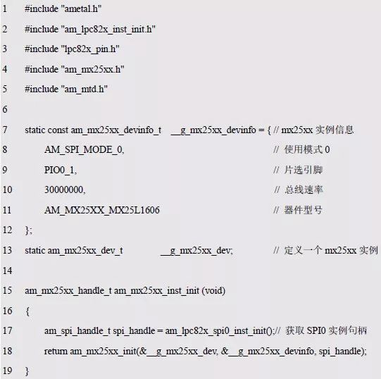
Based on the modular programming idea, the definitions of initialization related instances, instance information, etc. are stored in the corresponding configuration file, and the instance initialization function interface is extracted through the header file. The program examples of the source file and the header file are respectively shown in the program list 6.14 and the program. Listing 6.15.
Listing 6.14 Example Initialization Function Sample Program (am_hwconf_mx25xx.c)
Listing 6.15 Instance Initialization Function Interface (am_hwconf_mx25xx.h)
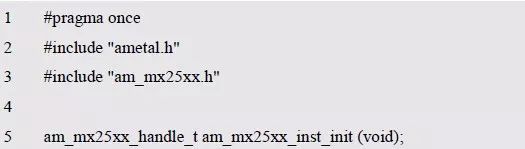
Subsequent only need to use the parameterless instance initialization function to get the instance handle of MX25xx. which is:

Note that spi_handle is used to distinguish between SPI0 and SPI1, and mx25xx_handle is used to distinguish multiple MX25xx devices in the same system.
>>>6.2.3 Interface function
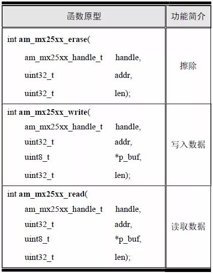
SPI Flash is special. Before writing data, you must ensure that the corresponding address unit has been erased. Therefore, in addition to the read/write function, there is an erase function. The interface function is shown in Table 6.6.
Table 6.6 MX25xx Interface Functions
The return value of each API has the same meaning: AM_OK means success, negative value means failure, and the reason for failure can be based on the specific value to view the corresponding macro definition in the am_errno.h file. The meaning of positive values ​​is defined by each API. If there is no special explanation, it means that it will not return a positive value.
Erase
Erase is to reset all data to 0xFF, that is, the bits of all memory cells are set to 1. The erase operation does not directly erase a single address unit. The smallest unit erased is a sector, that is, only one or more sectors can be erased at a time. The function prototype for erasing an address space is:

Where handle is the instance handle of MX25L1606, addr is the first address of the area to be erased, and since the smallest unit to be erased is the sector, the address must be the starting address of a sector 0x000000(0), 0x001000(4096) , 0x002000 (2 × 4096) ... At the same time, the erase length must be an integer multiple of the sector size.
If AM_OK is returned, the erase is successful, otherwise it fails. Assume that you need to erase 2 sectors consecutively starting from address 0x001000. See Appendix 6.16 for sample programs.
Listing 6.16 Erase Sample Program

0x001000 ~ 0x3FFF The space is erased, and data can be written to the segment address space.
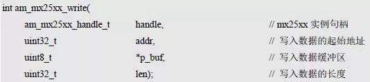
2. Write data
Before writing data, make sure the write address has been erased. The bit that needs to be changed to 0 is cleared to 0, but the write operation cannot change 0 to 1. For example, writing data 0x55 clears bit1, bit3, bit5, and bit7 to 0, and the remaining bits remain unchanged. If the stored data is already 0x55, then write 0xAA (write 0xAA is actually clear bit0, bit2, bit4, bit6 to 0, the remaining bits are unchanged), then the final stored data will become 0x00, instead of later 0xAA written. Therefore, in order to ensure normal data writing, it must be ensured that the corresponding address segment has been erased before writing data.
The function prototype for writing a piece of data starting from the specified starting address is:
If AM_OK is returned, the data is written successfully, otherwise it fails. Assume that 128 bytes of data are written consecutively starting from address 0x001000. See Appendix 6.17 for sample programs.
Listing 6.17 Write Data Sample Program

Although only 128 bytes of data are written, since the smallest unit erased is a sector, 4096 bytes (one sector) are erased. The erased area can be directly written to the data without having to erase it again, for example, immediately after writing the address after 128 bytes of data, and then writing 128 bytes of data, as shown in Listing 6.18.
Listing 6.18 Write Data Sample Program

If it is necessary to continuously write 128 bytes of data from the 0x001000 address again, since the data has been written before, it must be erased again before it can be written again.
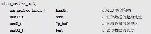
3. Read the data
The function prototype for reading a piece of data starting from the specified starting address is:
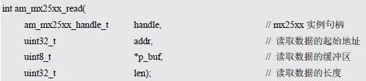
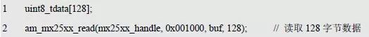
If the return value is AM_OK, the read is successful, otherwise it fails. Assume that 128 bytes of data are read consecutively starting at address 0x001000, as detailed in Listing 6.19.
Listing 6.19 Read Data Sample Program
The implementation and interface of the sample program are detailed in Listing 6.20 and Listing 6.21.
Listing 6.20 MX25XX test program implementation (app_test_mx25xx.c)
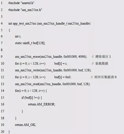
Since the cache space required for reading and writing data is large (128 bytes), the static modifier is added before the definition of the cache, so that its memory space is allocated from the global data area. If you allocate 128 bytes of space directly from the function's run stack, it is entirely possible to cause the stack to overflow and the system to crash.
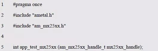
Listing 6.21 MX25XX Tester Interface Declaration (app_test_mx25xx.h)
The corresponding sample program is detailed in Listing 6.22.
Listing 6.22 MX25L1602 Read and Write Sample Program

Since the parameter of app_test_mx25xx() is an instance handle of MX25XX, it has a dependency on the MX25xx device, so cross-platform calls cannot be implemented.
>>>6.2.4 MTD Universal Interface Function
Since the MX25L1606 is a typical FLASH memory device, it is abstracted as a MTD (Memory Technology Device) that reads and writes the MX25L1606, making it independent of the specific device and enabling cross-platform calls. The function prototype is shown in Table 6.7.
Table 6.7 MTD Common Interface Functions
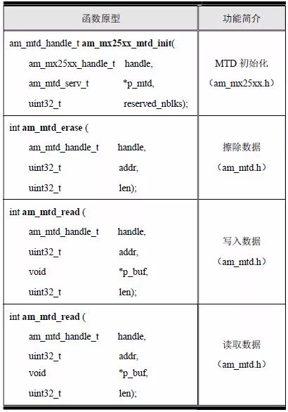
1 MTD initialization function
The MTD initialization function is intended to get the MTD instance handle. The function prototype is:

The MX25L1606 instance handle (mx25xx_handle) is passed to the handle as an argument, p_mtd is a pointer to an instance of type am_mtd_serv_t, and reserved_nblks is used as instance information to indicate the number of blocks reserved.
Instance (MTD storage device)
The definition of the am_mtd_serv_t type (am_mtd.h) is as follows:

Where g_mx25xx_mtd is a user-defined instance whose address is passed as an argument to p_mtd.
Instance information
Reserved_nblks represents instance-related information for the number of blocks reserved by the MX25L1606. These reserved blocks are not used by the MTD standard interface. The reserved block is calculated from the start block of the device. If the value is 5, blocks 0~4 of the MX25XX device will not be used by the MTD, and the MTD read and write data will start from block 5. This value is set to 0 if there are no special requirements.
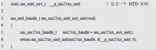
The call of the MTD initialization function is stored in the configuration file, and the corresponding instance initialization interface is extracted. See Listing 6.23 and Listing 6.24 for details.
Listing 6.23 adds the MTD instance initialization function (am_hwconf_mx25xx.c)
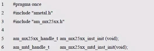
Listing 6.24 am_hwconf_mx25xx.h File Content Update (1)
The am_mx25xx_mtd_inst_init() function has no parameters, and the definition of its associated instance and instance information is done inside the file, so calling the function directly will get the MTD handle. which is:

In this way, when the other MTD generic interface functions are used subsequently, the return value mtd_handle of the function can be used as the argument of the first parameter (handle).
Obviously, if you use the MX25XX interface, call am_mx25xx_inst_init() to get the MX25XX instance handle; if you use the MTD generic interface, call am_mx25xx_mtd_inst_init() to get the MTD instance handle.
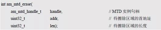
2. Erase
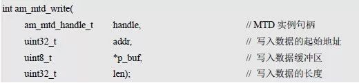
Before writing data, you need to ensure that the corresponding address has been erased. The function prototype is:
The size of the erase unit can be obtained using the macro AM_MTD_ERASE_UNIT_SIZE_GET(). such as:

Where addr represents the first address of the erased area and must be an integer multiple of the size of the erased unit. Similarly, len must also be an integer multiple of the size of the erased unit. Since the size of the MX25L1606 erase unit is the same as the sector size (4096), addr must be the start address of a sector 0x000000(0), 0x001000(4096), 0x002000(2×4096)......
If AM_OK is returned, the erase is successful, otherwise it fails. Assume that 2 sectors are erased consecutively starting at address 0x001000. See Appendix 6.25 for sample programs.
Listing 6.25 Erase Sample Program

After using this program, the address space 0x001000 ~ 0x3FFF is erased, and data can be written to the segment address space.
3. Write data
Before writing data, you need to ensure that the write address has been erased. The function prototype is:
If AM_OK is returned, the data is written successfully, otherwise it fails. Assume that the sample program for consecutively writing 128 bytes of data starting from the 0x001000 address is shown in Listing 6.26.
Listing 6.26 Write Data Sample Program

4. Read data
The function prototype for reading a piece of data starting from the specified starting address is:
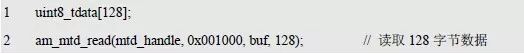
If the return value is AM_OK, the read is successful, otherwise it fails. Assume that the sample program for continuously reading 128 bytes of data starting from the 0x001000 address is shown in Listing 6.27.
Listing 6.27 Read Data Sample Program
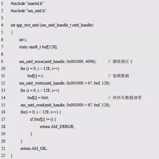
The MTD generic interface test procedures and interfaces are detailed in Listing 6.28 and Listing 6.29, respectively.
Listing 6.28 MTD test program implementation (app_test_mtd.c)
Listing 6.29 Interface Declaration (app_test_mtd.h)
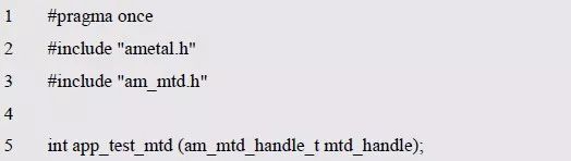
Since the program only requires an MTD handle, it is cross-platform multiplexed regardless of the specific device. If the result of reading and writing data is completely equal, it returns AM_OK, otherwise it returns AM_ERROR. For the sample program, see Listing 6.30.
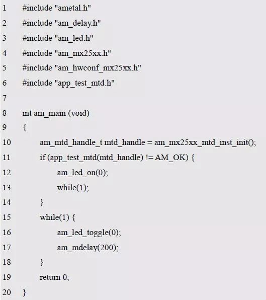
Listing 6.30 MTD Read and Write Sample Program
>>>6.2.5 FTL Universal Interface Function
Since the previous interface needs to ensure that the corresponding storage space has been erased before each data write, it will inevitably cause a lot of trouble for programming. At the same time, because the number of erasures of an address segment of the MX25L1606 exceeds the upper limit of 100,000 times, storing data in the corresponding segment address space will no longer be reliable.
Assuming that the user data is stored in a consecutive 4K address of 0x001000~0x001FFF, the address segment is re-erased each time the data is updated. The other storage space has not been used at all, and the service life of the MX25L1606 is greatly reduced. AMetal provides a common interface for FTL (Flash Translation Layer) for users to use. The function prototype is shown in Table 6.8.
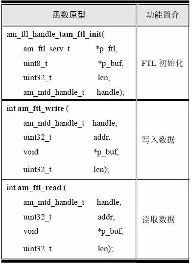
Table 6.8 FTL Common Interface Functions (am_ftl.h)
1. FTL initialization function
The FTL initialization function is intended to get the FTL instance handle. The function prototype is:

Among them, p_ftl is a pointer to the instance of am_ftl_serv_t type, p_buf and len are used as instance information to provide the necessary RAM space for the FTL driver, and the MTD initialization function obtains the mtd_handle as the MTD instance handle.
(1) Example
Define an example of the am_ftl_serv_t type (am_mtd.h) as follows:

Where g_ftl is a user-defined instance whose address is passed as an argument to p_ftl.
(2) Instance information
The FTL driver requires a certain amount of RAM space, which is also the price of using the FTL generic interface. Since the size of the space is related to the size of the specific device and the size of the erase unit, the memory space is provided by the user according to the actual situation. The required memory size (number of bytes) is obtained by the following formula:

Where sizease is the size of the erase unit, and for the MX25L1606, it is the sector size, which is 4096. Sizemtd_chip is the total capacity of the MTD instance. The MTD instance corresponding to the MX25L1606 is the size of the reserved block. If the reserved block is 0, it is the capacity of the MX25L1606, which is 2M. The required memory capacity is:

For the MX25L1606, if you use FTL, you need about 2.5KB of RAM. Obviously, for some small embedded systems, the cost of RAM is really too big, so choose whether to use FTL according to the actual situation. If the RAM is sufficient and you care about the lifetime of the Flash, you can choose to use FTL. The size of the capacity uses the macro in am_ftl.h:

This macro automatically calculates the actual RAM size based on the total device capacity and the erase unit size.
If you use the FTL common interface to operate the MX25L1606, you need to define the following memory space for FTL use. which is:

Where g_ftl_buf is the first address of the memory space, which is passed as the argument of p_buf, and the size of the memory space (that is, the number of array elements) is passed as the argument of len.
(3) MTD handle mtd_handle
This MTD handle can be obtained through the MTD instance initialization function. which is:

The obtained MTD handle can be passed directly as an argument to mtd_handle.
(4) Example handle
The return value of the FTL initialization function am_ftl_init () is the FTL instance handle, which will be used as the argument to the first parameter of the read-write interface. Its type am_ftl_handle_t(am_ftl.h) is defined as follows:

If the return value is NULL, the initialization fails; if the return value is not NULL, the valid handle is returned.
The call of the FTL initialization function is stored in the configuration file, and the corresponding instance initialization interface is extracted. See Listing 6.31 and Listing 6.32 for details.
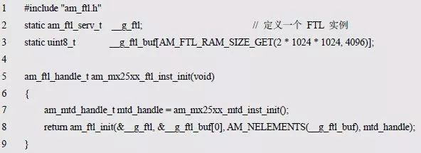
Listing 6.31 adds FTL instance initialization function (am_hwconf_mx25xx.c)
Listing 6.32 am_hwconf_mx25xx.h File Content Update (2)
Am_mx25xx_ftl_inst_init() has no parameters, and its definition of related instance and instance information is done inside the file, so calling this function directly can get the FTL handle. which is:

In this way, when the other FTL generic interface functions are used later, the return value ftl_handle of the function can be used as the argument of the first parameter (handle).
2. Write data
When the FTL general-purpose interface is called, the read and write data is in blocks, and the number of bytes per block of data is fixed to 512 bytes. Its function prototype is:

In order to extend the life of the Flash, data is written to the area with the least number of erasures during actual writing. Therefore, lbn is just a logical block number, which has nothing to do with the actual storage address. Logical blocks are just an abstract concept. Each logical block is fixed to 512 bytes in size and has nothing to do with the physical memory blocks of the MX25L1606.
Since each logical block of the MX25L1606 is fixed at 512 bytes, the number of logical blocks is 4096 (2 × 1024 × 1024 ÷ 512), and the effective value of lbn is 0 ~ 4095. However, in fact, each unit is erased by one logic block. The size of the MX25L1606 erase unit is 4096, that is, 512 erase units. Therefore, the FTL consumes 512 logic blocks, and the available logic block is 3584 (4096~ 512), the effective value of lbn is 0~3583.
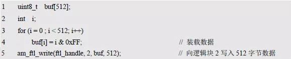
It can be seen that FTL not only occupies 2.5K RAM, but also 256K MX25L1606 storage space (512 logical blocks, each logical block size is 512 bytes), which is the "cost" to use FTL. If AM_OK is returned, the data is written successfully, otherwise it fails. Assume that a block of data (512 bytes) is written into Logic Block 2. The sample program is detailed in Listing 6.33.
Listing 6.33 Write Data Sample Program
3. Read the data
The function prototype for reading a piece of data is:
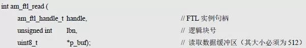
If the return value is AM_OK, the read is successful, otherwise it fails. Assume that a block (512 bytes) of data is read from Logic Block 2. The sample program is detailed in Listing 6.34.
Listing 6.34 Read Data Sample Program

The FTL generic interface test procedures and interfaces are detailed in Listing 6.35 and Listing 6.36, respectively.
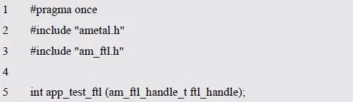
Listing 6.35 FTL test program implementation (app_test_ftl.c)
Listing 6.36 FTL Test Interface Declaration (app_test_ftl.h)
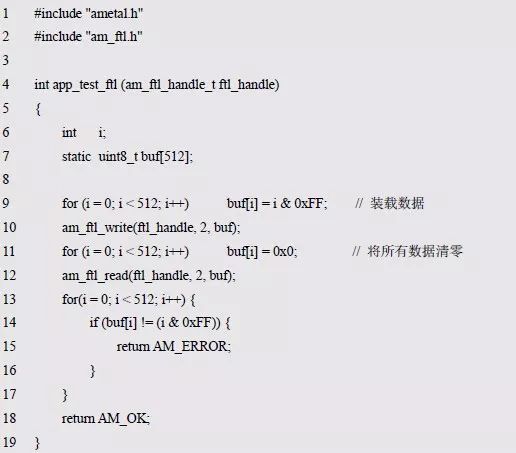
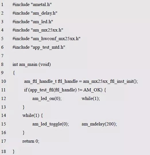
Writing an application is easier because there is no need to perform an erase operation before writing. Similarly, since the application only needs FTL handles, all interfaces are also FTL common interfaces, so the application can be reused across platforms. See Appendix 6.37 for sample programs.
Listing 6.37 FTL Read and Write Sample Program
>>>6.2.6 Micro Database
Since the hash table array space, keywords, and record values ​​used by the hash table are stored in the dynamic space allocated by malloc, this information is lost at the end of the program or after the system is powered off. In practical applications, it is often desirable to store information in non-volatile memory. A typical application is to store information in a file. Essentially, as long as the principle of the hash table is mastered, the way of operation is the same no matter where the information is stored.
In AMetal, a set of hash table interfaces that can be used directly is implemented based on non-volatile memory. Since data is not lost due to power loss or program termination, it can be regarded as a micro database. 6.9.
Table 6.9 Database Interface (hash_kv.h)
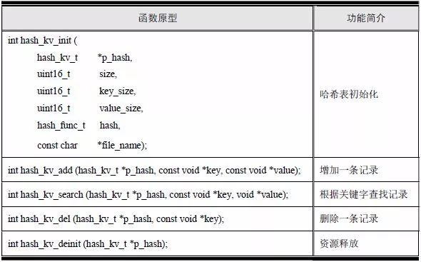
Obviously, except that the namespace is modified by hash_db_* to hash_kv_* (in order to distinguish it from the previous program), only the file name parameter is added to the initialization function, that is, the malloc allocation space is no longer used internally to store the record information, but The file specified with this file name stores related information. As a result, the record is stored in the file and the information is not lost due to power loss or program termination. Among them, hash_kv_t is the database structure type. Before using the database, you should use this type to define a database instance, for example, "hash_kv_t hash;".
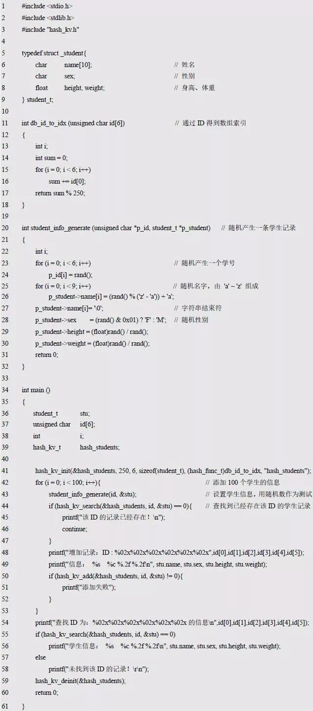
Since the functions of the functions are exactly the same as those of the hash table functions described in the book Programming and Data Structures, the code can be verified using the code shown in Listing 6.38.
Listing 6.38 Database Synthesis Sample Program
Power Bank,Pd Powerbank,Phone Powerbank,Rechargeable Power Station
suzhou whaylan new energy technology co., ltd , https://www.whaylan.com