In order to measure the time r, and in order to make the accuracy of the measured φ angle unaffected by the grid frequency (or period T), the interface circuit shown in the figure is employed.
The UCA line voltage signal obtained by the transformer TR and the line current iB signal obtained by the current transformer are all converted into corresponding square wave signals by the checker. After the voltage square wave signal is inverted by the G1 gate, it is added to the G3 gate input terminal as a gate pulse for measuring T/2 pulse width, and a positive square wave pulse with both UCA and iB being negative at the same time is obtained by the NOR gate G2. A gating pulse as the measurement time r is applied to the G4 gate input. The count pulse is obtained by dividing the ALE pulse of the 8031 ​​by four. Since the ALE pulse frequency is stable when the non-MOVX type instruction is executed in 8031, it is 1/6× crystal frequency. Therefore, the G3 and G4 gate output pulses can be counted by the 8031 ​​internal timer/counters T0 and T1. The waveforms and corresponding relationships of the above points have been shown in FIG.
In Figure 2, P3.0 of 8031 ​​is used to detect the UCA voltage zero crossing. When UCA crosses zero from positive to negative, corresponding to uc (ie P3.0) in Figure 1 changes from 0 to 1, the two counters T0, Tl start counting simultaneously; when UCA reaches negative to positive zero crossing, uc From 1 to 0, the counters T0 and Tl stop counting at the same time. Let T0 counter count value be N, T1 counter count value be n, and the measured phase angle φ can be calculated as follows:
The above calculation is easily done by the 8031. If the look-up procedure is further completed, the sine or cosine table is checked by the angle φ to obtain the power factor cosφ.

Block diagram
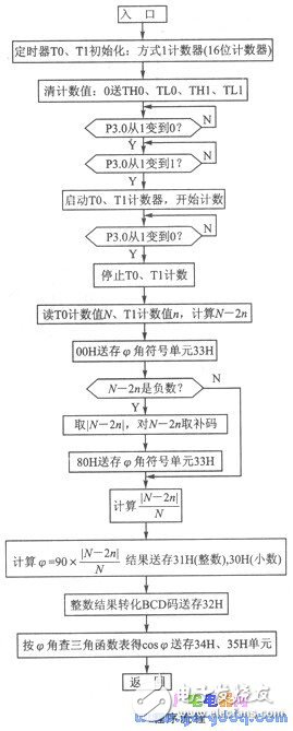
The program flow is shown in the figure below. Designed here as a subroutine form, after execution is completed, the binary integer of the φ angle is in 31H, the fractional part is in 30H, and the symbol is in 33H: OOH means resistive or inductive; 80H means capacitive. The decimal result of the φ angle is in 32H. Cosφ is in 34H, 35H.
When starting this program, regardless of whether the UCA is in the positive half cycle or in the negative half cycle, whether it is zero crossing or not, it can be ensured that the counting starts from the time when the uCA changes from positive to negative zero crossing, and stops when it changes from negative to positive zero crossing.
Litecoin (LTC) is a cryptocurrency created as a fork of Bitcoin in 2011. It uses a hashing algorithm called Scrypt that requires specifically designed mining software and hardware. It is minable, and continues to rank in the top cryptocurrencies for value and trading volume.
Litecoin mining is the process of validating transactions in the blockchain, closing the block, and opening a new one. Litecoin uses the proof-of-work consensus mechanism, which uses computational power to solve the nonce, which is part of the hash, that secures the block. The hash is the alphanumeric sequence of numbers that is encrypted by the hashing algorithm. When the nonce is solved, Litecoin is rewarded.
Litecoin mining became popular in 2011 when Charlie Lee, a software engineer at Google, announced its creation as a Bitcoin fork with modifications intended to help it scale more effectively.
Just like Bitcoin, it can be mined on computers using central processing units and graphics processing units. However, it isn't as profitable or competitive as purchasing an application-specific integrated circuit (ASIC) and joining a mining pool.
Ltc Asic Miner,Antminer L3 Plus Plus,Bitmain Antminer L3 Plus,Bitmain L3 Plus
Shenzhen YLHM Technology Co., Ltd. , https://www.ylhm-tech.com