1 Introduction With the rapid development of science and technology, people's daily necessities continue to develop in the direction of easy operation, easy to carry and intelligent. As an important daily necessities, TV is easy to operate, keyless, and intelligent. With the maturity of micromechanical accelerometer technology, its miniaturization, low power consumption, high precision, intelligence, and low cost make the application of TV remote control possible.
This design utilizes the characteristics of small size, rich functions, high precision and convenient and fast online simulation to realize simple and convenient control of the TV. The design uses a completely keyless design model that uses an accelerometer to accurately determine the direction of control. This remote control has two dimensions in four directions, namely four function keys. Through practice analysis, 4 keys can meet the basic operation of the TV. In the normal state, the X-axis direction is used for volume adjustment, and the Y-axis direction is used for channel adjustment. The system adopts battery pack power supply and adopts TV remote control universal coding. It is practical and convenient. It is suitable for the operation modes and habits of different people in the society. Its simple and low power consumption characteristics are the future development direction of TV remote control. The innovation of this design: realize the keylessness of the control system, realize the remote control with the direction quantity of the micro-mechanical accelerometer and the size of the vector on each side; the circuit design is unique and fully meets the design characteristics of the accelerometer performance; the product is small in size , battery-powered, flexible design, different degrees of change, can be applied to different occasions, different groups of people; through the software to achieve error correction and algorithm measurement of accelerometer.
This article refers to the address: http://
2 System structure The whole system mainly includes three parts: signal acquisition, processing and transmission. The design of each module directly affects the implementation of system functions. The analog signal output by the general accelerometer is weak. Due to the influence of internal and external interference in the system, the signal under test is mixed with interference signals. When the signal under test is very weak, it will be “submerged†by the interference noise, resulting in large data acquisition errors. Therefore the signal must be filtered before amplification. Amplify the signal to the appropriate range to achieve the highest possible resolution. In addition, the module should be as close as possible to the source so that the signal is amplified before it is affected by the environment, resulting in improved signal-to-noise ratio. The LM358 filter amplification circuit is used here. The amplified analog signal is then transmitted to the A/D converter and converted into a digital signal. Since the MCU has an A/D conversion function inside, the entire conversion process is implemented inside the MCU without adding an additional A/. D converter. At the same time, the single chip is used to analyze and process the signal; then the signal is transmitted through the RF transceiver module. The system block diagram is shown in Figure 1.

3 hardware circuit design The hardware of the keyless multi-function TV remote control mainly includes the accelerometer sensor unit, the controller unit and the infrared transmitting unit.
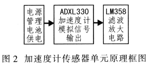
3.1 Accelerometer sensor unit The block diagram of the accelerometer sensor unit is shown in Figure 2. The three-axis accelerometer ADXL330 is used, which can measure the gravitational acceleration in three different directions simultaneously. The system uses only two output signals, the X-axis and Y-axis directions.
3.2 Controller Unit Figure 3 is a block diagram of the controller unit. The P30/AN00 and P31/AN01 pins of the controller receive the amplified sensor acquisition signal. The P60 to P67 and P00 to P07 pins are connected to the transmitter and transmit the transmission code. The MOD pin is externally connected to the jumper, and the corresponding voltage can be selected in the working mode or the download programming mode. The RST reset pin external button is used for system reset.

3.3 Infrared Emitter Unit The infrared emitting unit uses MC50462AP, which is powered by 5 V (AVDD) and transmits remote control code through the infrared diode port.
4 Software Design After power-on reset of the MCU, first judge whether the input port has analog signal input. If not, repeat detection and judgment. If there is, cycle the port signal. After the acquisition, the acquired signal is A/D converted in the single-chip microcomputer, and the converted digital signal is calibrated. For various reasons, the input acceleration signal cannot be in a single direction. Therefore, simplifying the process assumes that the input signal is always in a single direction. If multiple inputs are detected at the same time, each input will be compared and then a maximum value will be selected. As its only input. Finally, by analyzing the input, design the processing subroutine of each input and set its function.
Since the three-axis accelerometer can output acceleration values ​​in three different directions, different functions can be set for different inputs, each of which corresponds to a function and is embodied by a respective subroutine. Figure 4 shows the software design flow.

Since the system is powered by a battery, the system is in a sleep state when there is no signal input, and is in a working state when there is a signal input. After starting or resetting for 5 s, if there is no signal input, it goes to sleep to reduce power consumption.
It is verified by experiments that the average minimum acceleration of the artificial swinging remote controller is 1 g, that is, the calibration value set by the system is 1 g, and the acceleration is less than 1 g, which is considered to be an invalid signal. In this system, it is not necessary to specifically consider the elimination of input jitter, and jitter can be handled as a single input signal. The signal transmission completely adopts the transmission principle of the universal TV remote control. The internal oscillator of the microprocessor chip and the external oscillating crystal form a high-frequency oscillator to generate a high-frequency oscillation signal. This signal is sent to the timing generator to generate a sinusoidal signal and a timing pulse signal. The sinusoidal signal is sent to the coded modulator as a carrier signal; the timing pulse signal is sent to the command encoder as a modulated signal to be transmitted, and then modulated in the modulator and sent to the infrared light emitting diode VD to emit a pulse modulated signal.
5 Conclusion Introducing the design of a keyless remote control based on a micromechanical accelerometer. The product can control the TV with the motion posture, and the operation is simple and convenient, especially suitable for groups with inconvenient movement. At the same time, it has a strong expansion function, which can control the attitude of toy cars and electric toys and control the production of machine tools in the workshop. Due to the small size, low power consumption and low cost of microaccelerometers, similar devices have a wide market.
Rolling Shutter Forming Machine
Garage Door Forming Machine,Door Panel Forming Machine,Aluminum Shutter Slat Forming Machine,Shutter Door Roll Forming Machine
Haoshuo Technology Co., Ltd. , http://www.whrollformingmachine.com