1 Introduction With the increasing popularity of automated assembly lines, equipment in many plants needs to be upgraded. However, some old-fashioned devices have good functions, such as simple upgrades, can still play a huge role, thereby improving equipment utilization.
CCD can be used to realize the real-time monitoring function of old-fashioned testing equipment in the old-fashioned instrument retrofit. It uses CCD to image the traditional mechanical dial, replaces the human eye with the computer to complete the reading and discriminate work, and reduces the staff reading and data processing. The work has improved monitoring efficiency and real-time online monitoring and alarming.
This article refers to the address: http://
2 System working principle As shown in Figure 1, the CCD detection system is mainly composed of CCD camera, deck, light source, image acquisition card, computer and output device. The mechanical dial and the CCD camera are fixed by the card holder. The inside of the card holder is equipped with a light source to prevent the external environment from affecting the image quality, obtaining a relatively stable image, simplifying the computer processing process, and making the software simpler and more reliable. The obtained image is A/D converted by the image acquisition card. It is transmitted to a computer for software processing and identification, and the computer reads the obtained image and detects and monitors the collected data.
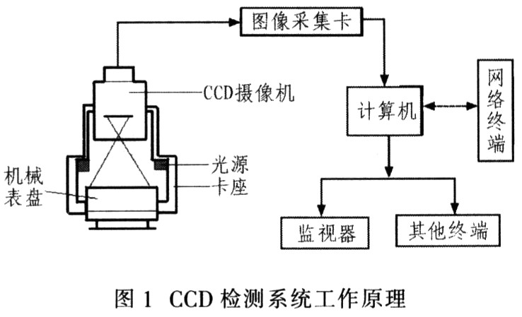
Since the device automatically reads the information of the mechanical dial into the computer, it uses the computer instead of the manual to perform a lot of processing work. For example, multiple readings for error analysis and processing; setting values ​​for early warning monitoring; remote monitoring of hazardous locations.
3 Select related hardware devices
3.1 Light source selection and card holder design Several LED Light-emitting diodes can be installed evenly around the inner wall of the card holder; ring-shaped and illuminating energy-saving lamps can also be selected to avoid the direct-directed CCD lens and the light source facing the CCD lens. There must be occlusion on one side. By designing the light source and the card holder in this way, the light can be uniformly illuminated on the dial, which is beneficial to the CCD to obtain a high-quality image, preventing the saturation of some CCD units and whitening the image portion and affecting the image processing.
3.2 CCD and lens selection According to the accuracy of the dial itself, the CCD is selected to ensure that the image can distinguish the minimum engraving of the dial, and the dial belongs to a small field of view, so a small size general resolution CCD can be selected. The CCD lens is matched with the dial size and field of view. The calculation formula is as follows:
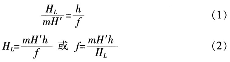
The same reason:
Where L is the field of view, HL is the horizontal direction of the field of view, VL is the vertical direction of the field of view, and f is the focal length.
4 Image processing software design Because the dial is close to the CCD lens and has a small field of view, it belongs to paraxial light imaging, and the image deformation is small. Pre-processing can be performed simply by filtering and denoising. Because VC++ is simple and fast, the processing program is developed under the VC++ environment using the Windows operating system as the platform.
5 Edge Detection Edge detection can be used to obtain the edge information of the hands, so that the outline of the image is more prominent, while the area outside the edge remains intact. The edge detection and enhancement processing weakens the low frequency portion of the image, the brightness of the processed image remains unchanged, the area where the pixel value changes slowly remains unchanged, and the area where the pixel value changes drastically is highlighted. Common edge detection methods include translation and differential edge enhancement, gradient direction edge enhancement, Laplace edge enhancement, and Sobel edge detection.
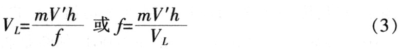
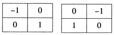
5.1 Robert detection operator The Robert operator computes the diagonal derivative on the 2 × 2 neighborhood, namely:


5.2 Krisch edge detection operator The Krisch edge detection operator uses eight modules to determine the gradient amplitude value and the direction of the gradient, which is expressed as:

As shown above, the operator convolves each point in the image with 8 convolution kernels, each convolution kernel maximizing the response to a particular edge direction, with the largest of all 8 directions as the edge image. Output.
The Krisch operator is a first-order differential operator used to detect the step edges of an image. The algorithm is simple, easy to program, sensitive to noisy edges, sometimes causing false contours or generating some non-existing edge points. For the roof type edge is invalid, the effect diagram is shown in Figure 3.
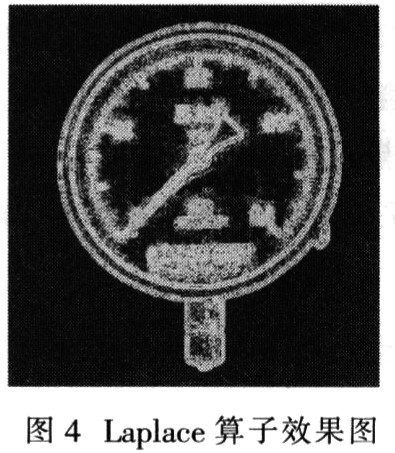
The zero-crossing point of the Laplace operator can also be used as a step-type edge point of the image, and its minimum value point can be used as the roof-type edge of the image. At the same time, since the noise point has a certain influence on the edge detection, the operator is a better edge detector, and its effect diagram is shown in FIG.
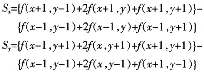
5.4 Sobel Detection Operator The Sobel Detection Operator is formed by two convolutions, namely:
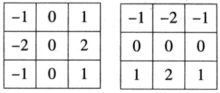
The operator combines the direction difference operation with the local average to calculate the partial derivatives in the x and y directions on the 3×3 neighborhood centered on f(x, y), ie:
 (5)
(5)
Equation (5) applies the weighted average difference of the image intensities of the f(x, y) neighborhood. The gradient amplitude is:

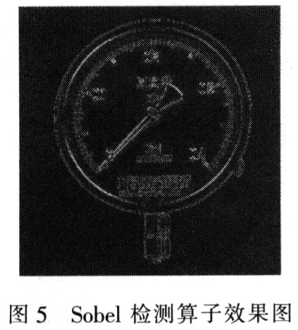
The Sobel operator believes that the influence of the neighboring pixels on the current pixel is not equivalent, so the pixels with different distances have different weights, and the influence on the operator results is different. The farther the distance is, the smaller the impact will be. The effect diagram is shown in Figure 5.
6 Algorithms related to the indication image processing of the instrument panel The related algorithms for the indication image processing of the instrument panel mainly include binarization processing and projection method recognition. In order to extract specific regions and information from complex images. The image needs to be simplified and segmented to separate the background (the area of ​​no interest) from the object (area of ​​interest).
The most common method of image segmentation is to divide the gray level of the image into different levels, then use the gray threshold (threshold) to binarize the image, segment the meaningful area, and convert the useful information into black, which is useless. The information is culled and converted to white. The area that is meaningful to the indicator table image is a pointer with a small (darker) gray value, while other dials with a larger (lighter) gray value are areas of no interest. Since the pointer of the indicator table and the dial have a large contrast in the actual situation, under uniform illumination conditions, it is easy to automatically search for a reasonable threshold to binarize the image, and the gray value is greater than the threshold. It is white, otherwise it turns black.
The design system adopts the following threshold selection algorithm: firstly, a threshold T(T≠0) is randomly determined, and then the gray average value v1 of the pixel whose gray level is larger than T and the gray average value v2 of the pixel whose gray level is smaller than T are respectively determined. Then find T'=(v1+v2)P2. Determine a termination condition, such as ε = 0.001, and determine if |T'-T| < ε. If not, the next round of operations is continued with T' instead of T; if so, the loop is jumped out with T' as the final threshold.
Each pixel in the binarized dial image is projected from the center along the radius to the circumference. The length of the projection represents the number of black pixels in the direction, and the longest point of the projection should be the position indicating the pointer of the table, and the point is found. The reading of the indicator table can be obtained by the correspondence relationship.
7 Conclusion The hardware part of the system is simple, the software algorithm has high reliability and high versatility. For different mechanical dials, add corresponding program function modules according to different requirements, select the card holders with different calibers, and after simple debugging, use. It is easy to implement and has a wide range of application values ​​in the production process.
Gift Flashlight,Led Flashlight,Mini Flashlight
Energy Electro Optic (Suzhou) Co., Ltd. , http://www.jsflashlight.com