Testing plays a very important role in today's automotive electronics development process. However, there are still many potentials in the industry for using the right strategies, ideas, and tools to make testing more efficient and automated in the future. This paper analyzes the current state of testing technology, clarifies the problems of interactions that occur in practice, and demonstrates that off-the-shelf tools can be used today to solve specific project tasks related to testing in an elegant and efficient manner.
This article refers to the address: http://
1 Introduction
In the past decade, the state of the automotive electronics industry has undergone tremendous changes. At first, only a few ECUs were used in the car, but now the number of ECUs installed in some luxury cars has exceeded 60 [JW1]. The added electronic system increases safety, comfort and energy savings. Today, more innovation relies on electronic technology, and the implementation of many features is increasingly dependent on software.
Increased complexity makes comprehensive and efficient testing more important than ever. The widespread use of a large number of electronic components has led to a dramatic increase in the number of potential sources of error. Because testing can detect and correct errors and reduce costs as early as possible, it is indispensable at all stages of ECU development. In addition, some system defects are exposed only when components are integrated and run in real-world and real-time conditions. This makes testing a cross-disciplinary and cross-vendor discipline.
The large number of electronic faults that occurred early on showed that what would happen if the above facts were not considered and system tests were ignored. The later the problem is discovered, the more serious the impact on raising costs. In the extreme case, product recalls due to correction errors more clearly illustrate this point. Although members of the automotive industry have learned these lessons and placed great emphasis on testing, we can still use existing resources to further improve testing efficiency. In addition, although the test cost occupies most of the project budget, it guarantees the correct function of the ECU. Therefore, it is important to use a clear concept (such as using modern methods and tools instead of incomplete automated test steps) to maximize test quality and test depth.
2. Analysis, simulation and testing tools
The ECU network is the backbone of automotive electronics. The residual bus simulation method establishes an important foundation for ECU testing. Without a preliminary simulation of the ECU environment, most ECUs cannot operate effectively. For example, many ECUs can only function properly if they provide network management functions.
CANoe from Vector Informatik is a tool widely used to analyze, simulate and test distributed, embedded systems (Figure 1). It is widely used in residual bus emulation and supports all important bus systems - in particular CAN, LIN, MOST and FlexRay - and Vector Informatik also offers PC interfaces for these bus systems. Existing commercial interface cards can be used to access the I/O lines of the ECU from CANoe. In addition, Vector announced that it will release an I/O hardware product with specific test features such as switching additional loads to the ECU terminal and directly shorting it.
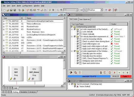
Figure 1: CANoe includes analysis, simulation, and testing capabilities for network systems.
The various analysis functions, simulation components, and test sequences depend on models that are integrated into the tool in the form of a database. They may be a communication matrix for DBC format for CAN, a FIBEX file for FlexRay, an XML function directory for MOST, or an LDF file for LIN. Similarly, CDD and ODX profiles can be used to describe the diagnostic functions of the ECU. In addition to the basic information of the system, the test description file contains symbolic names for signals, messages, and diagnostic services. This simplifies the work of testers and test developers and creates an abstraction layer between test and communication descriptions.
CANoe can be run on any simple PC workstation running Windows. Use a real-time configuration system to build a more powerful test station with higher real-time performance. The real-time configuration system consists of two parts (Figure 2): a dedicated computer running a real-time operating system (Windows CE) for performing residual bus simulation and actual testing; another stand-alone PC for use as a graphical user interface And conduct an assessment. In this setup, the system can also be used as a test execution environment for component HIL testing.
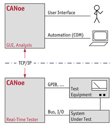
Figure 2: CANoe Real-Time with dual-machine operation provides higher real-time performance.
3. Integration of test and development
Today's development models require testing at all stages of development (Figure 3). Typically, individual testing is an independent, separate activity that is performed by dedicated personnel using specialized tools, languages, and methods on a suitably configured dedicated workstation. Here, creating a test is usually a separate job, separate from other development activities.
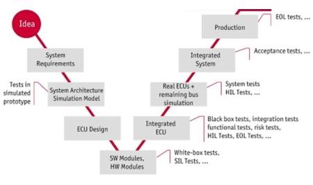
Figure 3: Testing is indispensable at all stages of development.
This segmented approach to work stems from the assignment of many different tasks in the development process to a dedicated workgroup. However, if the requirements for task segmentation are too strict, many of the associated points between different development and test tasks will most likely not be optimized for use. For example, only well-coordinated component testing and system testing can avoid the development of redundant test cases with the same content. When using compatible tools, test cases that have been developed can be used as a basis for development in other different areas. The practice of avoiding redundant development frees up resources that can be used, for example, in the validation of existing test cases and their advanced development. Comprehensive test management provides a solid foundation for collaboration, sharing the same test cases to optimize the breadth and depth of testing. Coordination also helps to identify and fill test gaps.
In addition to connecting different test phases, development and testing activities must also be interrelated and adaptable. Testing should be understood as an integral part of development, and it needs to be supported by appropriate methods and tools. In addition to the procedural and structural guarantees, this must be guaranteed. Here, it is important that testing is done with development, not just during the formal validation phase of the request. Ideally, you can test directly with existing resources directly at the ECU developer's work location.
To this end, CANoe provides a runtime environment for performing tests and can be used in parallel with residual bus emulation and analysis functions. This process is very easy to set up, especially if the developer has used CANoe for residual bus emulation and bus communication analysis.
CANoe's test components can be tested manually, semi-automatically and fully automated. Developers can start with simple tests and then extend and refine them. Often, the process of creating complex tests is the task of confirming the department, and they are building their tests on the developer's tests.
An important basis for this type of testing is residual bus simulation. Ideally, this simulation is not built manually, but is automatically generated and parameterized from the system's description database. The actual work is done by so-called modeling DLLs (such as interaction layers, network management, etc.) that are provided with the tool or provided by Vector as an OEM-specific modeling package. The signals provided by the residual bus emulation for the analog nodes can be obtained directly from the test script or manually motivated or added.
Tests accompanying development often omit formal execution and archiving compared to systematic planning, execution, and archiving activities in the testing phase. However, these tests have made a substantial contribution to improving overall quality because they give developers the ability to provide more stable products for subsequent testing phases.
4. Maturity assessment and error analysis
In the development process, in order to evaluate the maturity of the ECU, a comprehensive evaluation of all executed tests is required. In addition to considering the quality of individual test results in terms of reliability and relevance, it is more important to use appropriate tests to fully cover the required characteristics. Therefore, informal test results are also helpful for maturity analysis. The prerequisite is that (in addition to the recording test process) a compatible configuration management is used. This is also necessary from the perspective of completing a quality-oriented, structured development process.
No matter where or where (test lab or workbench), no user or test case developer intervention is required, and a test record is generated when the test is performed using CANoe. This eliminates the need for additional work when developing with tests. The XML used to test the records is an open format that other tools can use to process the results in more depth. For example, a test management system can be used to evaluate test records when performing maturity analysis.
The essence of this work is the mapping of test results to test cases, test cases to requirements. This can be easily accomplished using a unique identifier (such as a requirement ID) that the test case developer will reference in a single test case. CANoe will automatically copy the identifier into the test record so that all test cases, test results and requirements are clearly linked (Figure 4).
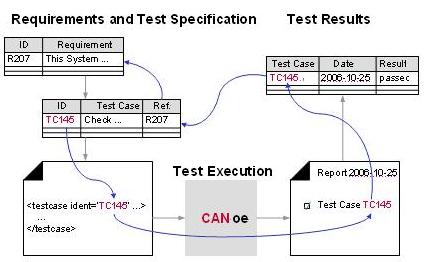
Figure 4: Test cases and test results are explicitly referenced by ID.
Analyzing the actual cause of the error is at least as important as recording and evaluating the test results. Most test tools don't provide such functionality or just provide some imperfect features. An important reason is that error analysis is often treated as a completely separate task for developers. First, they face problems that understand the errors detected in the tests and track their causes. Especially when the test lab reports an error, the developer is often unable to use the system used in the test.
For the above reasons, the test steps on the test bench and each interaction with the DUT will be forced to record, especially bus communication. During the analysis phase, CANoe allows playback and analysis of any required records (logs). It is thus possible to benefit from the same test system on the test bench at the development site, so that the developer can independently reproduce the test case that generated the error. In many cases, even when it is necessary to simplify (for example, to avoid the selection of non-existent measurement hardware), relevant test cases can be executed.
5. Signal abstraction and diagnosis
Abstraction is an important method commonly used in dealing with complexity issues in software development and system design. It can also be used to process tests. The ever-increasing number of functions in the ECU not only increases the complexity of the system, but also requires extensive and complex testing. Choosing the right abstraction layer composition test not only affects the amount of work required to create a test case, but also the cost, and can affect the quality of the test case. Like all other software components, the test case itself may have errors and should be checked before use. In addition, necessary maintenance is required, such as adapting to changes in requirements and revising test cases.
Signal layer abstraction is a common method of testing ECU functions, which is why actual applications in ECUs are often based on signal abstraction (Figure 5). For example, in a CAN system, the ECU interaction layer provides signal abstraction. This is how CANoe uses the interaction layer; it uses the information in the network description to parameterize itself. The network description can also be used to create ECU software. This ensures that the ECU and test environment use the same abstraction layer to achieve optimal coordination between the two.
The signal abstraction also represents -- at least in the protocol layer -- the residual bus emulation. For example, it ensures that periodic signals are sent on a periodic basis. In the test, the ECU is assumed to be placed in the real environment of bus communication. In addition, when the system communication matrix is ​​modified, it is usually possible to continue to use test cases that remain unchanged. For the same application, abstraction allows test cases in similar projects to be reused.
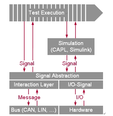
Figure 5: The signal provides an abstraction between the message and the I/O line on the one hand, and an abstraction between the test definition and the simulation model on the other hand.
In ECU testing, it is not just the signal interface that matters. Testing of many ECU functions makes sense only when deeper access to the ECU. Such access is provided by diagnostic and calibration interfaces that are accessed through the existing bus interface of the ECU. Since there is an established protocol under the communication process, it is meaningless to access these interfaces using a simple message sequence. It is more convenient and reliable to use appropriate diagnostic and calibration abstractions.
In CANoe, the parameterization of the access layer is responsible for the description file or ODX description file from the CANdela tool. If there is no description of the actual diagnostic capabilities of the ECU, a general description of KWP2000 and UDS provided by CANoe can be used. The general description files or diagnostic description files specific to the ECU facilitate the convenient access to the diagnostic services defined there, and the developer may obtain the same abstract data and advantages as in the signal abstraction above.
The measurement and calibration protocols CCP and XCP can be used to access the internal variables of the ECU through test scripts in CANoe. The measurement and calibration tool CANape handles these protocols and the required ECU description files (A2L). CANoe controls CANape through the COM interface. This achieves the same goals as in the signal abstraction and diagnostic abstraction above.
6. Efficient test generation
An in-depth study of test cases shows that many test cases can be generated from only a few loop modes. This is especially true in gateway ECUs: most test cases are used to check the routing of signals and messages. That is, the only reason to use a large number of test cases is that there is a large amount of possible input and output data. But the same type of mode is also present in other types of ECUs. This means that many functional tests are performed by first using the appropriate stimulus to bring the ECU into a special state and then checking the incoming state. The loop mode for this test case is: set the signal (excitation), wait for the maximum allowable response time, and then check the signal in the new ECU state. Based on experience with test patterns, users may identify several additional runtime patterns and generate many test cases from them.
The above pattern indicates that the generation of test cases has an opportunity to be further optimized. In addition to providing typical test case programming, CANoe also provides users with a way to define test cases based on test patterns. Since the test steps are known and integrated into the provided mode, there is no need to program the mode content (Figure 6). In this way, the generation of test cases is simplified to define the target behavior, including any additional data needed, such as the allowed setup time.
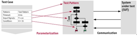
Figure 6: The usage pattern abstracts the actual execution of the test case to simplify test development.
Obviously, the test pattern provided is located above the signal abstraction described above, with the ability to provide symbolic access to signals, messages, etc., via an associated database, and the use of diagnostic services or I/O signals becomes possible. . In short: the entire CANoe test infrastructure can be shared with the test mode. If you really need more than these capabilities, you can also choose to program your test cases.
Automatic generation of test cases is another way to effectively create tests with the right source of information. Although the generated test content is necessarily limited by the level of description and the depth of the source. However, when testing covers the fundamental characteristics of a well-defined ECU, this test provides considerable support. Generating tests requires a small amount of work, which allows the tests to be performed faster and to detect problems earlier.
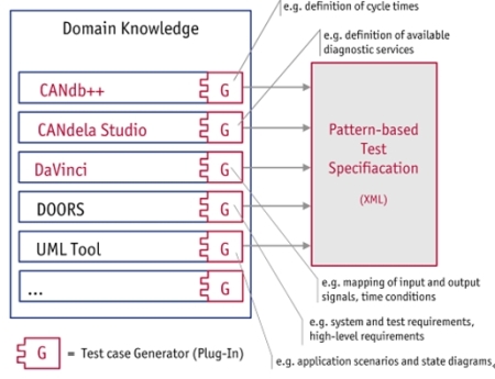
Figure 7: Using the generator you can create tests from completely different sources.
Vector's toolchain takes advantage of this test generator approach. A description file such as a DBC database or a CANdela definition is a resource for the generator (Figure 7). After using these files to generate test cases, CANoe can be executed immediately. Because test scripts may use the underlying structure of the entire tool, test generators are usually designed to be very simple. For example, a small number of work generators can be used to create appropriate test cases from user-defined gateway descriptions (such as database forms or Excel spreadsheets). With the test mode mentioned earlier, there is only one simple conversion from the customer's specific data to the test mode format. Users can create such generators directly. Vector provides further support in the form of project services.
7. Summary
The only way for automotive OEMs and suppliers to respond to increased ECU testing needs is to efficiently create tests and automate test execution. The test tools presented in this article provide a proven solution for implementing test tasks using signal abstraction/diagnostics/calibration/I/O interface integration, test pattern concepts, and test case generators. CANoe is a high performance real-time operating environment for testing ECUs and networks. Test developers can create and execute tests at an early stage with only a small amount of work at their own workbench. CANoe's open interface facilitates a seamless integration of comprehensive test strategies and tool-supported test management. Although some users regard it as a vision, as long as CANoe is properly integrated, perhaps this technology can reach maturity today. Vector is continually developing CANoe to accommodate applications in these areas and provides users with modern and efficient test platform support.
LED Floodlights,LED High Bay Light 500W,500W LED High Bay Light
Myled Electronics Technology Co., Ltd. , http://www.my-ledlight.com