The switching power supply has a high usage rate, and the superiority of the series-type regulated power supply cannot be compared.
This article refers to the address: http://
High efficiency: The regulating tube of the switching regulator power supply works in the switching state. Therefore, the power consumption is small and the efficiency can be greatly improved. The efficiency is usually about 80% to 90%.
Light weight: The switch-type regulated power supply is often directly rectified by the AC voltage input from the grid, eliminating the need for bulky power frequency transformers.
Wide voltage regulation range: When the input AC voltage changes between 80 and 260V, it can achieve good voltage regulation effect, and the output voltage changes below 2%, while maintaining high efficiency.
Safe and reliable: In the switching regulator circuit, there are various protection circuits.
The filter capacitor has a small capacity: the capacity of the filter capacitor is greatly reduced due to the high frequency of the switch signal.
Low power consumption and low internal temperature rise: Since the transistor works in the switching state, it does not need to use a large radiator, and the internal temperature rise is low, so the reliability and stability of the whole machine are also improved to some extent.
Switching power supply working state analysis
The switching power supply is divided according to the connection mode of the load and the energy storage inductor. Generally, there are a series switching power supply and a parallel switching power supply. The series switching power supply is prone to electric shock due to the defect that the grid voltage is not isolated from the main board ground. Most of them use parallel type switching power supply. The parallel switch power supply main board ground line is not connected to the power grid phase line. It is customarily called "cold chassis circuit" or "cold heart". At present, the most commonly used is the self-excited oscillation switch pulse width-regulated power supply, and some introduce the line synchronization function.

Figure 1: Schematic diagram of the working principle
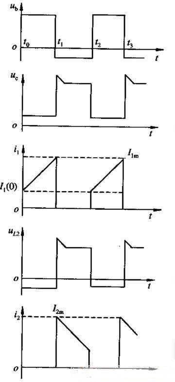
Figure 2: Waveform
It can be seen from the figure that as long as the on-time of the switching tube (that is, the pulse width is adjusted, the pulse width is adjusted) controls the charging time of the inductor L1, thereby controlling the amount of power supplied to the load, and the switching tube operates in the switching state. When the switch tube is turned off, the inductor L1 will generate a high self-inductance voltage, which is equivalent to the voltage of the power supply after rectification, about 3000V, so the switch tube voltage is required to be high, and the L1 has a suitable RC discharge loop.
The first 10 years of color TVs are mostly developed by Sanyo, and the main components are discrete components. However, the current color TV is in the form of an IC plus a switch tube, or directly in the form of an IC thick film.
Figure 3 shows the power supply part of the 2188F flat-panel color TV introduced by TCL in 2007, using an IC:
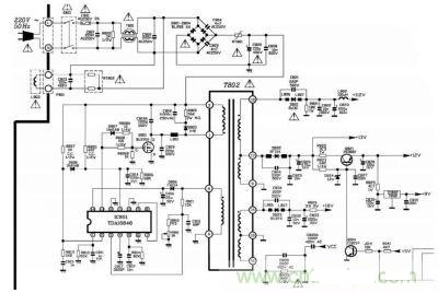
Figure 3: Power supply part of TCL's 2188F flat-panel color TV in 2007
TDA16846 adds a switch tube: the form of the FET BUZ91A, the whole circuit structure is relatively simple, this circuit does not use the optocoupler for feedback.
The general switching power supply of color TV is composed of three parts: oscillating circuit, voltage stabilizing circuit and protection circuit.
Oscillation circuit: The switching power supply oscillation circuit is divided into a transistor oscillation circuit and an integrated block oscillation circuit, such as STR-S series IC, TEA2104, TDA4601, TDA4605, TDA2261, TDA16846 and so on.
The voltage regulator circuit: the voltage regulation principle of the switching power supply adopts the pulse width adjustment type voltage regulation mode, that is, by automatically changing the ratio of the off and on time of the switching power tube, or by changing the duty ratio of the oscillator output pulse. The purpose of voltage regulation. The circuit of the voltage regulation part is composed of three parts: sampling, comparison and control. Many of the movements are made up of IC (such as SE110 and other IC) and optocoupler, while some movements are composed of discrete components (mostly Domestically produced machines, and some of the power ICs used in the movement integrate this part of the circuit (such as a partial series switching power supply IC).
Protection circuit: The color TV switching power supply is equipped with a protection circuit, and the protection mode is to make the circuit stop. Overcurrent protection, overvoltage protection and undervoltage protection (short circuit protection), as well as overheat protection. The overcurrent protection circuit has an overcurrent sampling point, and most of the television sets are at the emitter potential of the main vibration power tube. The sampling point of the overvoltage protection circuit is generally taken from the 220V AC rectified and filtered voltage or the main load supply voltage, and is sampled and determined by a Zener diode (stabilized tube). The sampling point of the short-circuit protection circuit is generally on the low-voltage group power supply output of the regulated power supply, and the diode is used for discriminating sampling. In the IC-type switching power supply, some of the power supply ICs used in the power supply IC have a "latch circuit" inside. The latch circuit is actually a protection execution circuit, a signal sent from each sampling point, through which the vibration stop control of the circuit is performed.
Switching power supply overhaul
After the switching power supply is damaged, most of them can be repaired independently, and all the loads are disconnected. A 22 V, 100 W bulb is used as a dummy load on the main load power supply, and a low-voltage power supply safety mode is adopted. The coupling transformer is reduced to about 70V for maintenance. This maintenance method completely avoids the phenomenon that the component is damaged again due to the hidden danger of the circuit. Generally, the normal switching power supply (parallel type) can normally start to vibrate at a supply voltage of about 70 V. Work, slowly adjust the output voltage of the autotransformer, the output voltage of the switching power supply should be fixed at its preset voltage value. If the output voltage of the switching power supply changes with the input voltage, it indicates that it is regulated. Partially problematic; if there is no voltage output, there is a problem with the oscillating circuit.
The first case: Let us discuss the maintenance method by taking the parallel type optocoupler to control the regulated switching power supply as an example. When the switching power supply cannot be properly regulated, the first step is to confirm the fault-causing part. The simple and quick method is to short-circuit the two control pins of the thermal coupling end of the optocoupler. If the circuit enters the vibration-stop state, it indicates that the fault is sampling. Comparing the circuit, the sampling comparison circuit is mostly caused by the damage of the IC and the optocoupler. (Comparative IC damage will cause the optocoupler to be damaged at the same time.) If it is a control circuit problem, such as control transistor damage, it must be replaced in the transistor. Pay attention to the parameters of the transistor.
The second case: the circuit does not vibrate. When you are sure that the power supply voltage is normal, first check whether the starting resistor (that is, the resistance between the 311V power supply and the base of the main vibration power tube) is open or variable. Also consider whether the vibration is due to the protection circuit action. Cause, such as STR6309 pin 6 voltage (normally 0 V), STR50213 pin 5 (normal 100V or so), TEA2261 pin 3 (normally 0V), TDA4601 pin 5, etc., if it is protected The circuit can cause the vibration to be stopped by this point, and when the control circuit has a problem (such as the breakdown of the control tube), the circuit will stop vibrating.
In fact, the switching power supply circuit is a relatively simple circuit, as long as the main vibration circuit, the protection circuit and the comparison voltage circuit are separated, the maintenance is easy.
In addition, the main vibration power tube of the switching power supply is inductive due to its collector, so when the main vibration tube is working, its collector will have to withstand 8 to 10 times the pulse voltage of the power supply, so an absorption circuit is added to the circuit. And the capacitors in the primary winding of the oscillating transformer and the resistors are connected in series) and the capacitors connected between the collector and the ground of the main oscillating tube. The function of these components has a similar effect to the reciprocal capacitance of the row output stage. When there is a problem, it is easy to damage the main vibration power tube. This point needs attention. I have repaired a Hitachi 2518 color TV. I found that the capacitance of the switching power supply absorption circuit increases when the temperature rises. Therefore, the fault of the main vibration power tube of the power source is often damaged, and the current limiting cement resistor is usually blown after the switch tube is broken down.
USB Data Charging Cable For Android
Usb Data Charging Cable For Android,Fireproof Braided Usb C Cable,Customizable Micro Usb Charger Cable,Zinc Alloy Type-C Data Cable
Dongguan Pinji Electronic Technology Limited , https://www.iquaxusb4cable.com