In the knowledge contest, cultural and recreational activities (competition events), the seat number of the respondent can be accurately, fairly and intuitively determined. Better promote the sense of competition of various groups, let the players experience the feeling of pressure on the battlefield
The traditional responder only judges the success or foul player number, and can't show the time of each player's answer. Now the responder can use data to explain the accuracy and fairness of the ruling results. The game has greatly increased the entertainment, but also more fair and just.
The addition of wireless responders is a major reform in the history of responders.
The software is more powerful:
With the new upgraded version of the software, the embedded PPT design can support the import of three format question banks (text document, WORD, Excel), the 15O track import is only 20 seconds, the imported topic is directly displayed in PPT mode, and can be directly displayed. The page is revised and the title is modified. This software also provides a variety of background templates for customers to choose from, click on any one to automatically import into the title. Very simple and convenient.
The accuracy of the answer is higher:
The first responder in China that can simultaneously display all the players' answer time and automatically sort them, with an accuracy of up to 0.00001 seconds. Create a new era in the field of answering questions, making the game uncontroversial and more entertaining.
Less host wiring: one
The main line is connected in series with all grouping score displays; minimizing the cumbersome wiring.
The answer mode is more complete: according to
The company's many years of experience in the competition, the various types of large-scale events used in the answer to the answer to four types: elimination mode, fast, direct, unlimited time, all included in this software, so the function is quite complete.
The answering rhythm is adjustable:
At present, the voices of the domestic answering machine are fixed, the customer can not adjust, the new responder adds adjustable function, the customer can adjust the game rhythm according to their own needs, and the software also provides two voice hosts for boys and girls. Mode, more humane.
Software operation is simpler: operation
In terms of various automatic identification functions, the game operation steps are simplified, and only 5 or 6 buttons can be used to complete the game during the official competition.
Electronic answering device
The central structure of the electronic responder is generally composed of a single-chip microcomputer and peripheral circuits. The matching accessories are divided into two parts: non-speech non-scoring responder and voice scoring responder.
It is more suitable for simple answering activities held by schools and enterprises.
The non-speech scorer is very simple in construction, which is composed of a host of a responder and a snap button. During the answering process, the player is a screen with no score.
The voice scorer is a display screen of the host and the host of the responder and a score display of the player.
Design of 6-channel responder for STC12C5A60S2Snatch button
According to the company's many years of experience in the competition, the answer box plays a very important role in the atmosphere of the game. Knowledge contest is a category of entertainment learning, so the atmosphere of the game is very important. The two technical indicators of the answer box can directly affect the game's air circumference: 1. How much is the answer box? 2, the size of the answer box.
1, grab the box line travel. Directly determine the atmosphere of the game, and decided to answer the box of 2 points: 1, the stroke of the mold. 2, the stroke of the button. The mold stroke should be 5~6MM is the best, and the button stroke is 2~3mm is the best, which can ensure the accuracy of the answer and ensure the atmosphere of the game. If the stroke of the answer box is less than 5mm, the player will appear too quiet when answering the question. From the scene, it is felt that the answer has been answered. However, the number of players who travel between 5 and 6 mm will be very large, and the atmosphere will be very lively.
2, the size of the answer box should be moderate, if it is too small, the general answer with the finger point to answer, so too light is not conducive to the atmosphere of the game, the company designed this answer box, apply the palm to vigorously beat to answer, this can be very Good to highlight the intensity of the game.
Overall design
By consulting a large number of relevant technical materials, combined with their own practical knowledge, I mainly proposed two technical solutions to achieve system functions. Below I will first explain the composition block diagram and implementation principle of the two schemes separately, analyze and compare their characteristics, and then explain the reasons for my final choice.
The answering device adopts STC12C5A60S2 (or STC89C52) single-chip microcomputer as the control core, and the responder can complete the operation control, signal recognition and display function realization. Because the MCU is used, the technology is relatively mature, the application is convenient and simple, and the auxiliary circuits around the MCU are relatively small, which is convenient for control and implementation. The entire system is extremely flexible and programmable, making it easy to expand and modify the functionality of the system.
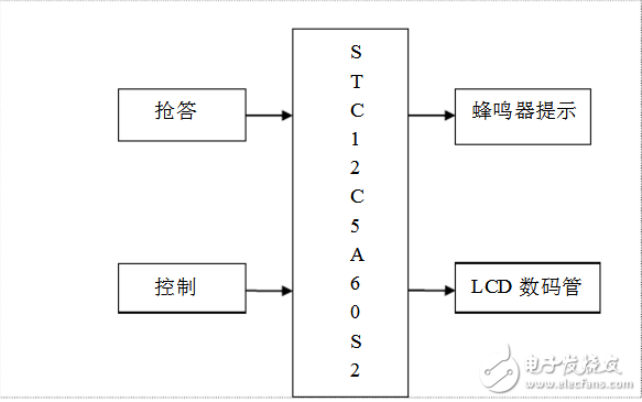
Answer circuit module
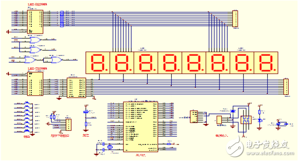
The working principle of the responder is to use the minimum system of the single-chip microcomputer, and use the query keyboard to answer. By answering the button module, the link button is used for answering. The working principle is as follows: after the host presses the clear key, the player can press the button to answer, the single chip latches the signal, shields the external signal, and at the same time displays the successful player number through the 5510, and the buzzer sounds. At this point, the timer works, and the answer countdown starts. At the end of the time, the host clears the system. The schematic is as follows:
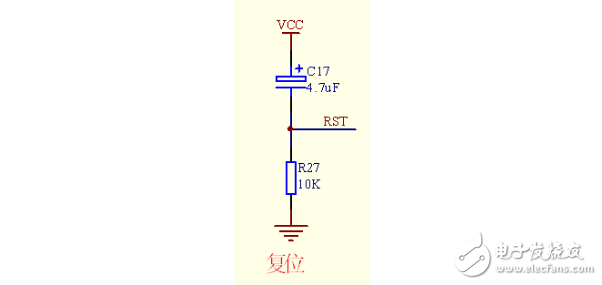
Reset circuit design
Reset circuit design The reset circuit adopts two kinds of reset modes: power-on automatic reset and manual reset. To achieve reset, it is only necessary to add a high level of 5ms to the RESET~I pin of the STC12C5A60S2 microcontroller. The power-on reset is realized by the charging of the capacitor, that is, the potential of the RESET terminal is the same as Vcc at the instant of power-on. As the energy storage on the capacitor increases, the capacitor voltage also gradually increases, the charging current decreases, and the potential of the RESET terminal. This establishes a pulse voltage that is adjusted to match the duration of the pulse. Usually, if a crystal of 12 MHz is used, the reset component parameters are 10 LI F electrolytic capacitor and 10 kΩ resistor. The button reset circuit is reset by pressing the reset button and the power supply to the RESET terminal to maintain a high level for two machine cycles.
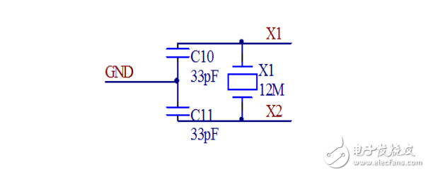
Crystal circuit design
The timing control function of the STC12 single-chip microcomputer is completed by the clock circuit and the oscillator, and the connection mode is divided into an internal clock mode and an external clock mode according to different hardware circuits. The internal clock mode has a high-gain inverting amplifier for forming an oscillator inside the microcontroller. The input of the high-gain inverting amplifier is the chip pin XTAL1 and the output pin XTAL2. These two pins are connected to the quartz crystal oscillator and the trimmer capacitor to form a stable self-excited oscillator. The circuit is shown in the figure.
Typical values ​​for capacitors C1 and C2 in the circuit are typically chosen to be around 30 pF. Although the value of the external capacitor is not strictly required, the size of the capacitor affects the frequency of the oscillator, the stability of the oscillator, and the speed of the start-up. The frequency of the crystal oscillator is usually between 1.2 MHz and 12 MHz. The higher the frequency of the crystal oscillator, the higher the clock frequency of the system, and the faster the operating speed of the microcontroller. This design uses an internal clock method.
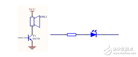
Buzzer alert circuit
The main reason is that when the MCU executes the interrupt, it can let the speaker work for a certain period of time in a short time when the signal is output. When the responder program responds, the triode is turned on, the buzzer's amplifier circuit is turned on, and at the same time, the horn sounds. Since the self-excited buzzer is driven by a DC voltage, it is not necessary to drive with an AC signal, and the buzzer sounds only by outputting a driving level to the driving port and amplifying the driving current through the triode. There are two ways to drive the buzzer by the MCU: one is the PWM output port direct drive, and the other is to use the I/O timing flip level to generate the drive waveform to drive the buzzer.
The PWM output port is directly driven by the PWM output port itself to output a certain square wave to directly drive the buzzer. In the software setting of the MCU, there are several system registers that are used to set the output of the PWM port. You can set the duty cycle, period, etc. After setting these registers to generate the waveform that meets the frequency required by the buzzer, just turn on the PWM. The output, the PWM output port can output the square wave of the frequency, and the buzzer can be driven by this waveform at this time. For example, if the buzzer with a frequency of 2000 Hz is driven, it can be known that the period is 500 μs, so that only the PWM period is set to 500 μs, and the duty level is set to 250 μs, a square wave with a frequency of 2000 Hz can be generated. The square wave can then use the triode to drive the buzzer.
Using the I/O timing flip level to generate the drive waveform is a bit more cumbersome. You must use the timer to make the timing. The timing flip level generates a waveform that matches the frequency required by the buzzer. This waveform can be used to drive. The buzzer is out. For example, for the 2500Hz buzzer driver, you can know that the period is 400μs, so that only the I/O port that drives the buzzer can be flipped once every 200μs to generate a frequency of 2500Hz and a duty cycle of 1/2 duty. The square wave can be driven by the triode to drive the buzzer. When the buzzer sounds, the illuminating two laser lights up.
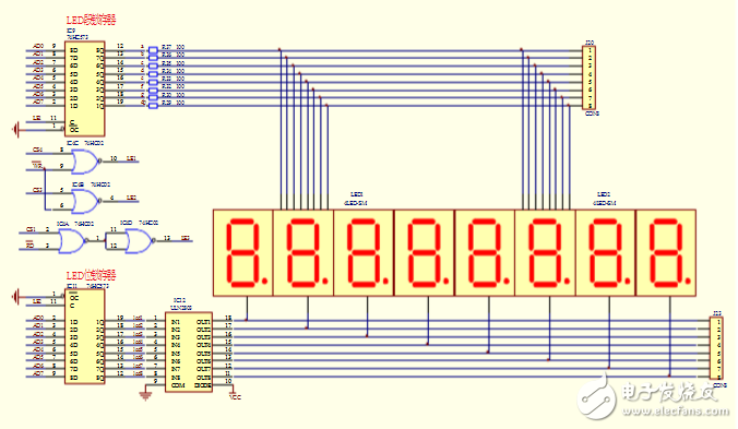
Display circuit
The display circuit can be implemented by an LED or an LCD. Here, ULF-3461BS is used for display.
Power circuit
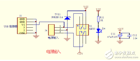
Download program interface
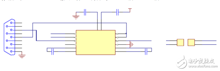
The program download interface of this system is a single power supply level conversion chip MAX232 designed by Maxim for the RS-232 standard serial port of the computer, and is powered by a single power supply of +5v.
The first part is the charge pump circuit. It consists of 1, 2, 3, 4, 5, 6 feet and 4 capacitors. The function is to generate two power supplies of +12v and -12v, which are required for RS-232 serial port level. The second part is the data conversion channel. Two data channels are formed by the 7, 8, 9, 10, 11, 12, 13, and 14 feet. Among them, 13 pins (R1IN), 12 pins (R1OUT), 11 pins (T1IN), and 14 pins (T1OUT) are the first data channels. 8 pins (R2IN), 9 pins (R2OUT), 10 pins (T2IN), and 7 pins (T2OUT) are the second data channels. The TTL/CMOS data is converted from T1IN and T2IN input to RS-232 data from T1OUT and T2OUT to the computer DB9 plug. The RS-232 data of the DB9 plug is converted from R1IN and R2IN input to TTL/CMOS data and output from R1OUT and R2OUT. The third part is power supply. 15 pin GND, 16 pin VCC (+5v).
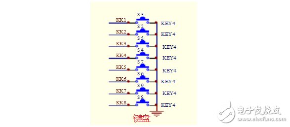
Keyboard circuit
Keyboards come in many forms. Such as independent buttons, matrix keyboard, encoding keyboard and so on. Often in daily development
Use the keyboard. But the keyboard will take up a lot of IO, for example, 4 * 4 matrix keyboard, will use the 8 IO ports of the microcontroller. The AD keyboard not only uses the AD conversion chip, but also converts the analog voltage value output by the keyboard, and then transfers the converted digital quantity to the single-chip microcomputer, so that 7 IO ports can be saved, and the MCU can flow out the remaining IO ports for other peripheral circuits. use.
Program initialization: After power-on, set the interrupt entry and other status flags of the microcontroller, clear the relevant interrupt flag, initialize the external display circuit, and the display will light. Port setting and initialization: Off the display circuit, the button circuit corresponds to the I/O port output LOC for button detection.
The answering process: display countdown, scan to valid button press, countdown stop countdown, enter the answer countdown, buzzer sounds 10S, and then wait for reset. If the valid button is not scanned during the rush time, it will count down until the countdown is zero. If the buzzer sounds for 10 seconds, the buzzer will sound “no answerâ€. Key scan: Dynamic scan is used to detect button press, software debounce, and then confirm the button. End of the answer: Clear the relevant signs of the call, clear countdown and channel answer confirmation display.
Silver-zinc Rechargeable Battery
Silver Zinc Rechargeable Battery,Battery For Aircraft Standby Power,Professonal Silver Zinc Battery,22.5V 45Ah Silver Zinc Battery
Henan Xintaihang Power Source Co.,Ltd , https://www.taihangbattery.com