The picture shows the charging adapter circuit of a digital camera. The circuit uses a pair of transistor differential amplifiers and a current amplifier. Output constant voltage and required current respectively. Transistors T1 and T2 form a pair of differential amplifiers. The base voltage of T1 is stabilized at 3V by the Zener diode ZD1. The base voltage of T2 is obtained by the power supply through R3 and R4. T1 and T2 compare the base voltage with each other, and adjust the base current of the current amplifier T3 accordingly.
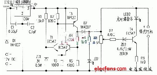
Digital camera charging adapter circuit diagram
Transistor T3 is connected as a current amplifier to provide sufficient current for charging. T3 uses TIP127. It is a medium power Darlington transistor with a current amplification factor of 1000. Therefore, if the base current of T3 is 1mA, the collector current will be 1A at most. T3 is connected to the working mode of the inverting amplifier. Therefore, when a positive voltage is applied to the base of T1, a negative pulse will be output to drive T3 after T1 is turned on. R2 provides a current of about 1mA to the base of T3. So the T3 collector will output 1A.
100Ω R3 plays an important role in the process of adjusting the output voltage and current of the differential amplifier. The current through R3 is the sum of the emitter currents of T1 and T2. Since the collector of T2 is directly connected to the 6V power supply, its collector current is fixed.
Therefore, the base current of T3 changes with the current flowing through R2 and R3. This design can stabilize the charging voltage and current. Any changes in the output voltage are detected by transistors T1 and T2, and the base current of T3 is adjusted accordingly.
The power supply of the adapter is obtained from a 12v car battery through a cigarette lighter socket. Regulator chip 7806 (IC1) reduces the 12V input voltage to 6V and limits the output current to 1A.
The bypass capacitors C1 and C2 should be close to the pin of Ic1 when soldering. Ic1 must add an appropriate heat sink to dissipate heat.
LED1 and LED2 are used to indicate "charging" and "charging full" respectively. When the digital camera is connected to the adapter, LED1 glows to indicate "charging", while LED2 remains off. The function of the 4.7V Zener diode ZD2 is a diode switch. It only drives T4 into a conductive state when the battery terminal voltage exceeds 5.3v (= 4.7v + 0.6v), causing LED2 to emit light, indicating "charge is full". Whether the rechargeable battery reaches 5.3v can be adjusted with VR1. D1 and D2 in the figure are used for polarity protection.
The circuit can be installed on an ordinary PCB board. And put in the appropriate box. Insert the plug of a car phone charger into the cigarette lighter socket in the car.
Wedge is the specific way to seal the bulb base. It is applied on many different types of bulb, such as T5, T6.5, T10, T13, T15 and T20. T5 bulb is usually be used as dashboard. T10 bulb are usually be used as interior lights, side indicators, front parking lights, 3rd stop light, glove compartment lights and license plate lights. T15 are usually be used as 3rd stop light, stop lights, rear Fog Light and reversing light. T20 are usually be used as front indicators, front parking lights, 3rd stop light, rear indicators, reversing light and stop lights. To get more detailed information, please contact with our sales representatives. We will reply with you as soon as possible.
Auto Wedge Base Lamp
Auto Wedge Base Lamp,Car Interior Light,Car Width Light,Concave LED Light
Heshan Jianhao Lighting Industrial Co., Ltd. , https://www.sunclubtw.com