Compared with ordinary light sources, LED lamps have the characteristics of high efficiency, environmental protection and long service life, so they are becoming the main solution for reducing energy consumption of indoor and external lighting. The switching power supply designed for lighting power supply should also have high efficiency in order to comply with the energy-saving characteristics of LED lamps. In addition to the high power conversion efficiency during normal operation, the standby power consumption of the switching power supply has also become a common focus of the LED industry. In the not-too-distant future, standby power consumption is expected to be adjusted below 1W or even 300mW. However, in LED lighting applications, auxiliary power levels dedicated to standby power supplies are not suitable, mainly because lighting applications do not have standby conditions during operation. However, even when there is no lamp or the lamp is damaged, the switching power supply that supplies power to the bulb is still connected to the power grid and draws energy. This is the main reason for concern about standby power levels in lighting applications.
In an empty office building, a lighting system with poor standby power consumption characteristics is not environmentally friendly. This article discusses how to introduce a simple auxiliary circuit to reduce standby power consumption. The proposed circuit can realize the intermittent operation of the power factor correction (PFC) level, which is necessary to reduce the standby power consumption of the lighting switching power supply. In order to evaluate the proposed circuit, we designed a two-stage switching power supply with a rated power of 120W, which can obtain standby power consumption of less than 1W under a wide input voltage range.
Two-level configuration
Due to the rated power and the need to improve the power factor, the switching power supply of LED street lights usually uses a two-stage configuration, which is composed of the first-stage PFC module and the second-stage downstream DC-DC converter. In the medium power range around 100W, the critical conduction mode (CRM) is a suitable control scheme for the PFC stage. In this rated power range, downstream DC-DC converters usually use a quasi-resonant flyback topology. The highly integrated FAN6300 pulse width modulation (PWM) controller has an internal valley voltage detector, which can ensure that the power supply system operates in a quasi-resonant state within a wide line voltage range, and reduces switching losses, so that the The switching voltage is minimized. To minimize standby power consumption and improve light load efficiency, a proprietary green mode function provides off-time modulation to reduce the switching frequency and perform extended valley voltage switching to ensure that the MOSFET is turned off The drain-source voltage is kept to a minimum. Using this feature, the second DC-DC stage enters the intermittent operation mode under no-load conditions, and can obtain very ideal standby power consumption characteristics. Most existing PFC controllers do not have intermittent operation functions, mainly because the PFC stage is initially aimed at consumer applications and display applications, and in those applications the auxiliary power supply that provides voltage sources for the PFC and DC-DC stages is separate. In LED lighting applications, the auxiliary power stage is usually not used. Therefore, the PFC stage should be turned off, otherwise the standby power consumption cannot be lower than 1W.
PFC level intermittent working mode
In the two-stage switching power supply, the PFC stage should be turned off to meet the requirements of standby power consumption regulations. The main reason for shutting down the PFC stage is that most PFC controllers do not have intermittent operation (Burst-Operation) characteristics. If the PFC controller does not support the intermittent operation mode, the PFC stage will work continuously, even under no-load conditions, it will draw energy. Therefore, for a two-stage switching power supply design with an existing PFC controller, turning off the PFC stage is the only feasible method. However, when the PFC stage is restarted, a large inrush current occurs, which causes an increase in voltage or current stress on power switches such as MOSFETs. In addition, it will cause the LED lamp to flicker during constant current operation. The industry needs to find a new way to meet the standby power consumption regulations, while avoiding the above problems. A feasible method to solve these side effects caused by completely shutting down the PFC stage is to use the intermittent working mode of the PFC stage.
It is recommended to use a simple auxiliary circuit to synchronize the operation of the PFC with the quasi-resonant flyback DC-DC converter, because when the DC-DC converter starts intermittent operation, the PFC stage can also enter intermittent operation mode. Once the second-stage flyback converter ends the intermittent mode operation, the PFC stage will immediately exit the intermittent mode. Figure 1 shows the working principle of the auxiliary circuit. The bias power supply of the PFC stage is controlled by the feedback of the quasi-resonant flyback DC-DC converter.
Figure 1: Proposed circuit for intermittent PFC-level operation
Under no-load conditions, when the feedback voltage of the flyback converter drops, the power supply voltage of the PFC stage is cut off and the PFC controller stops working. Figure 2 shows the working waveform of the load from full load to no load, and then to full load. Once the second-stage flyback converter enters intermittent operation, the PFC stage enters intermittent operation mode and stops intermittent operation mode in synchronization with the flyback converter. By performing intermittent work on the PFC stage, large surge currents that may cause potential problems can be eliminated, and standby power consumption can be greatly reduced. In order to evaluate the intermittent operation of the PFC level, a FAN7930 critical conduction mode PFC controller, a quasi-resonant flyback controller with intermittent operation function FAN6300A and the proposed PFC control circuit were used to design a 120W (48V) for LED street lights /2.5A) LEB-016 demonstration circuit board. As shown in Figure 2, the proposed circuit works well. Table 1 shows the measured values ​​of standby power consumption under various input line voltages. It can be proved that in a wide input range, standby power consumption can be reduced by more than 80%. It can also obtain standby power consumption of less than 0.3W at high line input voltage.
Figure 2: Enter intermittent work (left) and return to full load work (right)
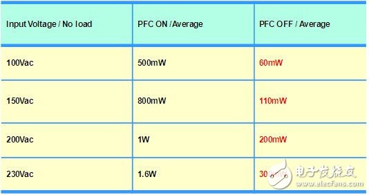
Table 1: Standby power consumption
in conclusion
This is a simple but very effective method to improve the standby power consumption of lighting switching power supply. This proposed circuit can make the PFC stage and the second stage DC-DC converter work intermittently. This method eliminates the inrush current problems associated with shutting down and restarting the PFC stage. The proposed circuit can effectively reduce the standby power consumption. Through the evaluation of the circuit board, it is verified that the standby power consumption can be less than 1W in a wider input voltage range. The proposed method is very attractive for lighting applications where there is usually no standby power regulation module.
Guangzhou Ehang Electronic Co., Ltd. , https://www.ehangmobile.com