1 Introduction
In the high-fidelity audio circuit, the tube amplifier has always been loved and concerned by the majority of audio lovers because of its unique charm and music listening. In recent years, high-fidelity headphones have been favored by more and more music lovers and audiophiles due to their convenience and relatively low price. In the high-fidelity earphone family, the impedance of the earphones is distributed from low resistance, medium resistance to high resistance: such as love technology's 271S rated impedance is 48Ω, Beyerdynamic's Dt48 rated impedance is 200Ω, Senhaier's HD580, HD600, HD650 The rated impedance is 300Ω. For earphones with high impedance, special matching circuits are usually needed to show their excellent performance. Compared with the speaker unit used for the sound box, the earphone has stricter requirements for its driving circuit performance index. Compared with the transistor, the static working point of the tube has a high voltage and a large internal resistance, which is more suitable for outputting a drive signal with a large swing and a small current. This feature makes the tube suitable for driving high-fidelity headphones with high quality requirements but low power requirements.
In the audio preamplifier, the ShuntRegulated Push-Pull (SRPP) circuit has the characteristics of high gain, low distortion, low output impedance, etc., and can obtain excellent sound quality performance, so it is widely used in audio circuits. This article designs a headphone amplifier circuit with a common cathode amplifier as the input stage and an SRPP amplifier circuit as the output stage. A micro-variable equivalent model is established for this circuit, a reasonable device is selected, and the corresponding parameters are controlled through theoretical calculations, so that the amplifier can better drive the headset to work.
2 Input level
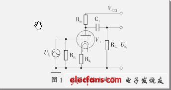
The input stage uses a common-cathode amplifier circuit composed of an electron tube triode, and its circuit schematic is shown in Figure 1. The resistors RL1, Rk1 and Rg1 in the figure are connected to the anode, cathode and grid of the electron tube respectively, so that the electron tube establishes a stable working point, and at the same time has appropriate gain and appropriate local negative feedback. V1 can choose commonly used electronic transistors, such as single transistor ECC92, or one transistor in double transistor ECC82, 12AU7, 5814 and other models. The working principle is different from the bipolar transistor in the transistor, but it is similar to the field effect transistor. Voltage-type amplifier device, its main parameters are transconductance gm, internal resistance rp and amplification factor μ, and the three meet:
The micro-variable equivalent circuit of this circuit is shown in Figure 2, where the electron tube is regarded as a controlled voltage source. In the figure, the input voltage can be expressed as:
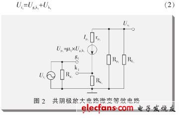
In formula (2), Ug1k1 is the voltage across the grid and cathode of the tube, and Uk1 is the voltage across the cathode resistance Rk1:
3 output stage
The output stage adopts SRPP circuit. The electron tube can choose the transistor with proper internal resistance, such as 6N6, E182CC, or the low-power pentode for power amplifier, such as 6P15, 6P14, EL42, EL91, EL84, EL86.
Generally, the internal resistance of the pentode is large, and the gain is high. In order to reduce the output impedance and gain, the pentode needs to be connected as a triode.
The output stage in the article uses low-power pentode as the amplifier device. When choosing other types of tubes, the parameters of the peripheral components and the supply voltage VCC2 need to be determined according to the parameters of the tube itself. In FIG. 3, Rsg1 and Rsg2 respectively connect the second grids and anodes of the pentodes V2 and V3, thus becoming a triode working mode. Rk2 and Rk3 are connected to the cathodes of V2 and V3, respectively, to provide proper grid negative pressure for the electron tube. RL2 represents the impedance of the load. When choosing different types of tubes, due to the difference in internal resistance and gain, there will be different sound performance when driving headphones, and the choice of tubes can usually be determined by subjective sound quality evaluation.
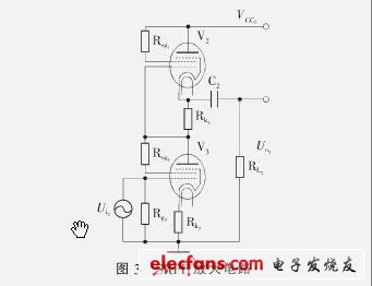
Fig. 4 is the slightly variable equivalent circuit of Fig. 3, where Ip is:
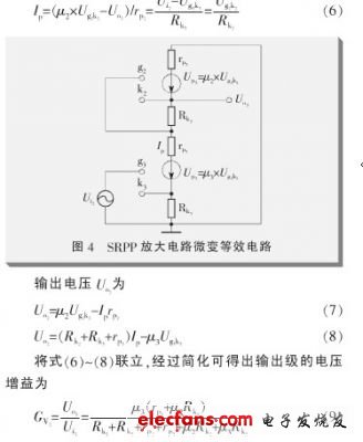
A voltage U′o2 is applied to the output, and the current looking inward from the output is recorded as I′o2, which can be calculated from equations (10) to (12):
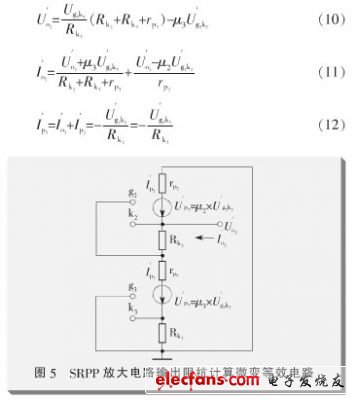
The output impedance of the SRPP amplifier circuit can be calculated from equations (11) to (13):
![]()
High quality back housing cover replacement for IPhone Back Cover Housing.
We will be responsible with Lifetime Replacement in 12 months Warranty.
Replace your broken or unusable item with a new one, make your device look more refreshing than ever.
Professional installation is highly recommended, each item has been checked and in good condition before shipping.
Advantages:
1. Large stock, fast delivery, can meet large purchasing plan.
2. Original top quality.
3. Complete fit and work.
4. Supply quality warranty with professional service.
IPhone Back Cover Housing,IPhone Back Cover Assembly,IPhone Replacement
Shenzhen Aokal Technology Co., Ltd. , https://www.aokal.com