The city's road network is complex and interwoven, with traffic lights serving as a critical command system for urban traffic management. As an effective tool for regulating traffic flow and increasing road capacity, traffic lights play a significant role in reducing traffic accidents. However, traffic volume fluctuates constantly, while traditional traffic light systems rely on fixed-time control, which can lead to congestion during peak hours.
This paper presents a smart traffic light system that adjusts the switching time of traffic lights based on typical commuting patterns. During peak hours, the red light duration is set to 40 seconds, while it is 60 seconds in normal conditions. This adaptive approach helps reduce the occurrence of long red lights during rush hours, allowing vehicles to move more efficiently and alleviating traffic congestion.
**1. Traffic Management Scheme Demonstration**
In 1968, the United Nations "Road Traffic and Road Signs Signal Agreement" defined the meaning of various signal lights: a green light allows passage, a red light prohibits movement, and a yellow light serves as a warning that the green light is about to change. For clarity, we assume two main north-south roads intersecting at a crossroad. To ensure pedestrian safety, four sidewalks—A, B, C, and D—are designated. As shown in Figure 1.
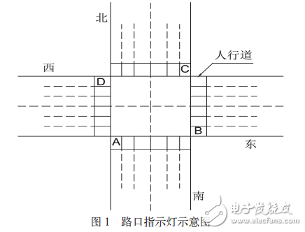
*Figure 1: Diagram of the intersection indicator*
The intersection operates as follows: when the east-west roads are red, vehicles are prohibited from passing, but pedestrians on sidewalks B and D may cross. At this time, the north-south roads are green, allowing vehicles to pass, while pedestrians on A and C must wait for 60 seconds. After that, the yellow light flashes for 5 seconds, signaling the upcoming switch from green to red. When the east-west roads turn green, vehicles can proceed, and pedestrians on B and D are restricted. Simultaneously, the north-south roads turn red, and pedestrians on A and C are allowed to cross. This cycle ensures orderly vehicle movement and safe pedestrian crossings.
**2. Design of the System Hardware Circuit**
**2.1 Overall Outline of the System Circuit**
This design consists of an 89C52 microcontroller, a traffic light display module, an infrared receiving module, a digital tube, and buttons. The 89C52 acts as the central controller, coordinating the operation of other modules. Buttons and the infrared module allow users to switch between normal mode and peak mode. In normal mode, the red light lasts 60 seconds, while in peak mode, it is reduced to 40 seconds. The traffic light display guides vehicles, and the digital tube shows the remaining time, helping pedestrians decide whether to cross or wait. The block diagram is shown in Figure 2.
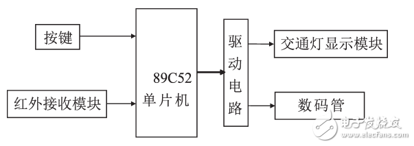
*Figure 2: System design block diagram*
**2.2 Hardware Circuit Design**
**2.2.1 Selection of the Controller**
As the core of intelligent traffic control, the choice of controller is crucial. Common options include FPGA, PLC, and 51 series microcontrollers. While FPGA and PLC offer high performance, they come at a higher cost. For practical applications, the 51 series MCU provides good performance at a lower price. Therefore, the well-known 89C52 microcontroller is used as the system controller.
**2.2.2 Infrared Emission and Reception Principle**
The universal infrared remote control system comprises a transmitter and receiver. The working principle involves converting the optical signal into an electrical signal, amplifying it, and then demodulating it to restore the original code. This process is illustrated in Figure 3.
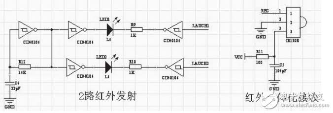
*Figure 3: Schematic diagram of infrared emission and reception*
**2.2.3 Overview of the Hardware Circuit**
The system uses the 89C52 microcontroller to manage operations. It supports two modes: normal and peak. Mode switching can be done via a button or infrared remote control. The button is suitable for on-duty personnel, while the infrared remote is ideal for traffic police inspections. The microcontroller controls the digital tube to display the time and manages the traffic light colors through P1^2–P1^7. The hardware circuit is shown in Figure 4.
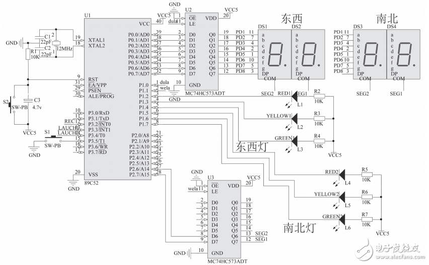
*Figure 4: Hardware circuit diagram*
**3. System Software Design**
The initial setup includes timer configuration and parameter initialization:
```c
#include
#define uint unsigned int
#define uchar unsigned char
uint aa, num, MODEL1, numa, HMODE1;
uchar shi, ge, gTime, rTime;
sbit dula = P1^0; // segment selection
sbit wela = P1^1; // position
sbit LED1 = P1^2; // East-West Red
sbit LED2 = P1^5; // North-South Red
sbit LED3 = P1^6; // North-South Yellow
sbit LED4 = P1^3; // East-West Yellow
sbit LED5 = P1^7; // North-South Green
sbit LED6 = P1^4; // East-West Green
sbit KEY1 = P3^5;
uchar code table[] = {0x3f, 0x06, 0x5b, 0x4f, 0x66, 0x6d, 0x7d, 0x07, 0x7f, 0x6f};
uchar table1[] = {0xbf, 0x7f};
void delay(uchar z) {
uchar x, y;
for(x = z; x > 0; x--)
for(y = 110; y > 0; y--);
}
void init() {
TMOD = 0x01; // Timer 0, 16-bit mode
TH0 = 15536 / 256;
TL0 = 15536 % 256;
EA = 1; // Enable global interrupt
ET0 = 1; // Timer 0 interrupt enable
TR0 = 1; // Start Timer 0
aa = 0;
gTime = 60;
rTime = 40;
num = 1;
numa = 1;
MODEL1 = 1;
HMODE1 = 0;
}
```
**Timing Function and Principles**
When the MCU is in timing mode, the timer counts machine cycles. With a crystal frequency of 12MHz, each machine cycle is 0.001ms. The timing function calculates the initial value of the timer to achieve the desired delay.
**Display Subfunction**
The MCU selects the latch to control the segment and position of the digital tube, displaying the required numbers. This ensures accurate time display for both vehicles and pedestrians.
M12 splitter can provide an easier connection of field components and clear wiring. In addition to the M12 thread full plastic dispenser, we also offer 7/8" dispensers. Main cable connection can be based on needs to choose ascrew connection or convenient direct connection. Use Y - type distributor to double the junction box socket. Thus, the wiring time and workload can be saved and the field signal distribution can be simplified.
M12 Distribution Box,M12 junction Box,M12 4 Way Distribution System,M12 junction box 8 way,M12 distribution box PNP NPN
Kunshan SVL Electric Co.,Ltd , https://www.svlelectric.com