Multisim Simulation Design of Crossroad Traffic Light Control Circuit System

In modern cities, the traffic volume on urban roads is high, often leading to serious traffic congestion. To address this issue, especially at intersections where traffic lights cause major bottlenecks, it's essential to enhance the traffic light control system. This paper presents a design for a crossroad traffic light control circuit system. We utilized virtual instruments in a virtual laboratory to simulate and design the traffic light control circuit using MulTIsim, an advanced EDA simulation tool. MulTIsim is a powerful software that offers comprehensive simulation capabilities for both analog and digital circuits. It provides a user-friendly Windows-based environment for building and testing electronic designs. With its interactive schematic entry and real-time simulation features, MulTIsim plays a crucial role in the design and verification of electronic systems. **1. Principle of Traffic Light Controller** Consider a crossroad with two intersecting roads, A and B. The traffic light control method operates as follows: Road A starts with a green light (3 seconds), followed by a yellow light (1 second), while Road B remains red (4 seconds). Then, Road A turns red (4 seconds), and Road B gets a green light (3 seconds) followed by a yellow light (1 second). One full cycle lasts 8 seconds. A synchronous decimal counter, specifically the 74LS160, is used to manage the timing, effectively functioning as a modulo-8 counter. **2. Circuit Design** **2.1 Truth Table** Assuming that the green, yellow, and red lights for Road A are represented by GA, YA, and RA, and for Road B by GB, YB, and RB respectively, the truth table for the traffic light control circuit is shown in Table 1.

Table 1: Traffic Lamp Control Circuit Logic Truth Table

Multisim Simulation Design of Crossroad Traffic Light Control Circuit System

**2.2 Designing a Modulo-8 Counter** **2.2.1 Introduction to 74LS160** The 74LS160 is a synchronous decimal counter with a standard pin configuration. Pins A, B, C, D are preset inputs, LOAD is the preset control, CLR is the asynchronous clear, ENP and ENT are the enable terminals, CLK is the clock input, RCO is the carry output, and QA–QD are the decimal outputs. When ENP, ENT, and LOAD are set to high, the chip operates in counting mode.

Multisim Simulation Design of Crossroad Traffic Light Control Circuit System

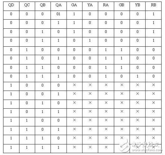
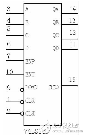
Figure 1: 74LS160 Pin Distribution Diagram

**2.2.2 Modulo-8 Counter Design** When a 1 Hz pulse is applied to the CLK terminal, the counter generates an 8-second control signal. To create a modulo-8 counter, the count range should be from 0000 to 0111. A NOT gate is used to convert the 1000 signal into a clear signal, which resets the counter via the CLR pin.

The designed circuit is shown in Figure 2:

Multisim Simulation Design of Crossroad Traffic Light Control Circuit System

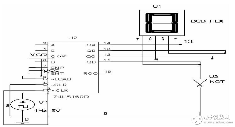
Figure 2: Modulo-8 Counter Connection Diagram

**2.3 Deriving Logical Expressions** Using the truth table, the logical expressions for each lamp can be derived using the logic converter in MulTIsim. These expressions are:

Multisim Simulation Design of Crossroad Traffic Light Control Circuit System

**2.4 Implementing the Logic Circuit** Based on the logical expressions, the corresponding logic circuit is constructed, as shown in Figure 3.

Multisim Simulation Design of Crossroad Traffic Light Control Circuit System

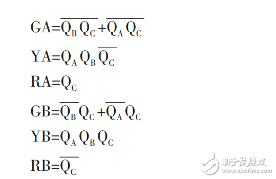
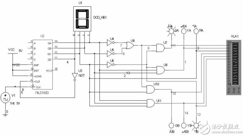
Figure 3: Traffic Light Control Circuit Logic Connection Diagram

**3. Circuit Simulation** By selecting the simulation menu and accessing the logic analyzer, we set the maximum time interval to 0.001 seconds and the clock to 1 Hz. The simulated waveform is displayed in Figure 4.

Multisim Simulation Design of Crossroad Traffic Light Control Circuit System

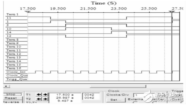
Figure 4: Traffic Light Control Circuit Logic Simulation Diagram

As shown in the figure, the output matches the expected behavior from the truth table, confirming that the circuit design is correct.

**4. Conclusion** By utilizing the virtual simulation tools available in MulTIsim, we were able to efficiently derive the logical expressions of the circuit, significantly improving the design process. The logic analyzer also allowed us to verify the circuit’s performance in real-time. This approach not only saves time but also makes it easier to adjust and test the design before implementation. The proposed circuit is practical and can be implemented in real-world traffic control systems.

PEW Enameled Aluminium Wire

About PEW Enameled Aluminium Wire

We product class 155 enameled aluminium wire from 2.65-6.0 mm.

According to the characteristics of motor, transformer, automotive electrical and high-speed winding machine, we have advantages in resilience, breakdown voltages and have imported machine to protect the quality of Enameled Copper Wire.

Enameled Aluminum


Name

Enameled Aluminum Wire

Conductor

Aluminum

Dimension

Diameter(mm): 2.65 ~ 6.0

Thermal Class(℃)

130(Class B); 155(Class F); 180(Class H); 200(Class C); 220(Class C+);

Standard

IEC; ISO9000; ISO9001; IATF16949

Packing

PT4 – PT200 or ply-wood spool

Application

Transformer; motor; generator; modern instrument; welding machine and so on.


Class 155 heavy insulation thickness of modified polyester enameled aluminum round wire


Wire Of Motor,Pew Enameled Aluminium Wire,Aluminum Wire For Coils,Enameled Clad Aluminum Wire

HENAN HUAYANG ELECTRICAL TECHNOLOGY GROUP CO.,LTD , https://www.huaonwire.com

Posted on