This paper realizes the connection control of AD9959 frequency synthesis chip through C8051F020 single-chip microcomputer, and combines a small number of peripheral circuits to form a complete frequency synthesizer with low noise, low power consumption, high stability and high reliability. The direct frequency synthesizer of this signal source will control the register of the AD9959 chip by programming the standard SPI port of the single chip C8051F020, thereby realizing the linear frequency modulation 3-way coherent signal output of single frequency point 12MHz, 48MHz and bandwidth 30MHz.
1 System design and functional unit introduction
1.1 System design
The main control chip of this design adopts C8051F020 single-chip microcomputer of Xinhualong Company. The signal generation chip adopts AD9959 which has 4 channels of DDS chip of American Analog Devices, and the power supply part adopts the regulated switching power supply which can provide 5 V and 3.3 V. The design block diagram of the system is shown in Figure 1.

1.2 AD9959 chip
The AD9959 is a new four-channel, low-power, high-speed direct digital frequency synthesizer from Analog Devices, Inc., with sampling rates up to 500 MSPS. The chip integrates four DDS cores to independently program four internal synchronous output channels. The individual channels are synchronized internally by the chip through a common system clock, each with a power of less than 165 mW. Up to 16 levels of frequency, phase and amplitude modulation (FSK, PSK, ASK) can be achieved. The modulation level can be controlled by applying data to the configuration pins. In addition, it can also work in linear sweep, sweep or sweep mode. Applied to radar and measuring instruments, it can also effectively correct the imbalance of external signal channels due to analog processing (such as filtering, amplification) or PCB wiring mismatch.
The device integrates four high-speed 10-bit DACs with outstanding wideband and narrowband SFDR characteristics. Each channel has a 32-bit frequency control word, a 14-bit phase control word, and a 10-bit output amplitude control word. It is widely used in local oscillator sources, phased array radar / sonar systems, measuring instruments / meters, synchronous clocks and RF signal sources. Its characteristics are as follows:
(1) There are 4 DDS channels with 10-bit DACs, the highest sampling frequency is 500 MSPS;
(2) Each channel has independent frequency/phase/amplitude control functions;
(3) Channel isolation greater than 65 dB;
(4) Linear frequency/phase/amplitude scanning function;
(5) Frequency/phase/amplitude modulation up to 16 levels;
(6) The DAC can both scale current and independently program;
(7) 0.116 Hz or better frequency adjustment resolution;
(8) 32-bit frequency resolution;
(9) 14-bit phase shift resolution;
(10) 10-bit output amplitude scalable resolution;
(11) Serial I/O port (SPI) with enhanced data throughput;
(12) The power saving mode can be controlled by software/hardware to reduce power consumption;
(13) Dual power supply (DDS core 1.8 V, serial I/O 3.3 V);
(14) Built-in multi-device synchronization function;
(15) Built-in clock multiplying phase-locked loop (4 to 20 times multiplier);
(16) The reference clock source can be selected.
2 system software design
2.1 programming process
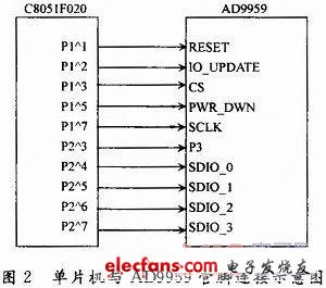
In this system, several I/O ports of P1 and P2 of C8051F020 single-chip microcomputer with SPI bus are mainly used. The connection diagram between them and AD9959 is shown in Figure 2.
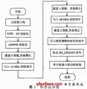
In the main function of the MCU programming, the watchdog must be turned off first. Otherwise, whenever the breakpoint is executed, the program will jump to the entry point and execute it from the beginning. Then initialize the microcontroller's clock (using external high-precision, high-stability crystal oscillator 22.118 4 MHz) and I / O port configuration, then initialize the AD9959 through the I / O port, select the channel, write the corresponding control word, send I The /O_UPDATE signal outputs the desired signal. The program flow chart of the single chip microcomputer is shown in Figure 3.
12V100Ah Lithium Ion Battery,Deep Cycle Solar Battery,2V 100Ah Lifepo4 Battery,12V 100Ah Lifepo4 Battery Pack
Jiangsu Zhitai New Energy Technology Co.,Ltd , https://www.zttall.com