This article describes a sound card with a USB interface, the effect is quite good, the circuit is also very simple.
This article refers to the address: http://
Circuit principle
The circuit schematic is shown in Figure 1.
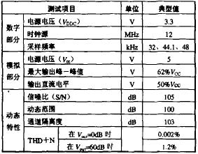
   PCM2702 (IC1) is a USB interface DAC chip produced by BB Corporation of TI Corporation. The PCM27O2 supports the USB1.0 standard and can receive 16-bit stereo or mono USB audio data streams. The basic parameters are shown in Table 1. IC2 is an integrated dual op amp for output buffer amplification.
The left side of IC1 is the digital input part, the right side is the analog output part, and the 2nd leg of PCM2702 requires a voltage of 3.3V. Here, it is subtly depressurized with a red light-emitting tube, and doubles as a power supply indicator, as long as it is plugged into the USB port, it is Will be lit, and connected to R1 is to reduce the burden on the LED. R2 is a pull-up resistor. Considering the high frequency ripple of the power supply provided by the computer, strong filtering measures are adopted. C3 ~ C11 and C18 are power supply filtering and decoupling capacitors, plus an inductor for the analog part of the filter.
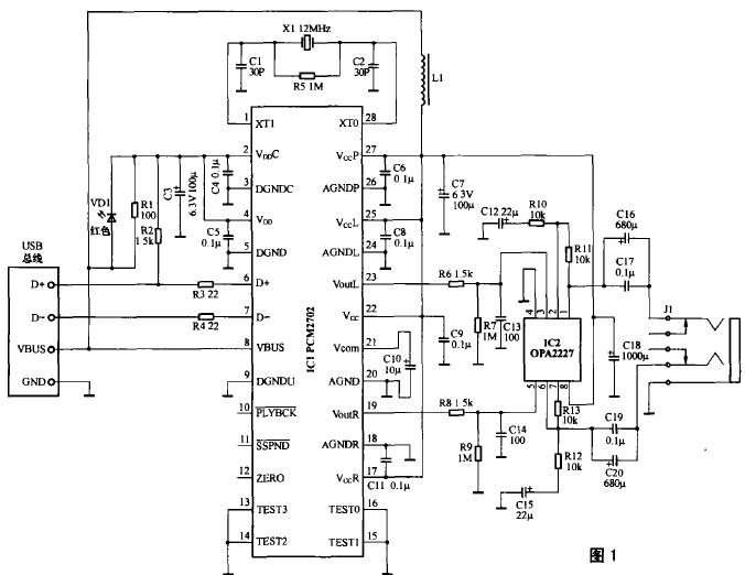
The audio output of the PCM2702 is biased from 1 to 2Vcc. Since the buffered op amp is a single-supply application, there is no DC blocking capacitor, so the op amp does not need to be biased. IC2 constitutes a buffer amplifier with a DC amplification factor of 1, and an AC amplification factor of 2. C16, C17, C19, and C20 are DC blocking capacitors. If the op amp output resistance is ignored, the calculation formula of the DC blocking capacitance is as follows:
C=7/(6Ï€f L R L )
Where f L is the lower limit frequency and R L is the load impedance. If the lower limit frequency is set to 40 Hz, the two headphones are used in parallel. Since the impedance of a common headphone is usually 32 Ω, then RL is 16 Ω, and the value of the DC blocking capacitance can be calculated. For 580.5uF, here 680uF, and a 0.22uF CBB capacitor can improve high frequency sound quality. Of course, since the PCM2702 output has a large amplitude, it can directly push a small power amplifier such as the TDA2282, so the op amp can be changed to a power amplifier, so that the output power will be larger.
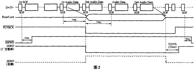
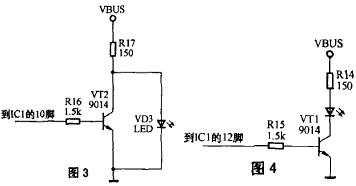
Pins 11 through 13 of the PCM2702 are status flag pins. According to the information given by the manufacturer, the 10-pin state is high when there is no audio signal, and becomes low when the first frame of the second frame of audio data arrives until the first frame of the second frame becomes high after the audio data ends. Level. As long as there is data input, 11 feet are high. The 12-pin is at a high level from the beginning of the first frame of the data to the start of the second frame, and is low after the normal input of the audio data signal thereafter, or if the audio signal continues for 1024 sampling periods of zero, Is high. Figure 2 is a timing diagram of the status of these three pins. Accordingly, the signal outputted by the 10-pin can be applied to an inverter to drive the LED for operation indication, as shown in FIG. However, when playing music, it is found that during the entire audio data stream input process, the 12-pin is always maintained at a high level, and once the music is stopped, the 12-pin becomes a low level. Therefore, the work indicating circuit can also be driven by the 12-pin signal. At this time, the circuit is as shown in FIG. 4. These two application schemes have strict indication meanings with respect to the latter, but the power consumption is slightly larger.
Component selection
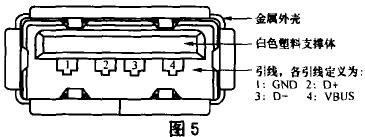
All electrolytic capacitors withstand voltage should be above 6.3V, and the resistor power should be 1/4W in addition to R17, and the remaining 1/16W can be used. C12, C15, C16, C17, C19, C20 have a great influence on the sound quality, and high-quality capacitors should be used. L1 can be made by itself, and it can be wound around a small core (column, ring) with a thick enameled wire around 10åŒ. For ease of use, in this circuit, the supply voltage is taken directly from the USB 5V positive supply. Therefore, a low-voltage op amp should be used, and it is best to use a single-supply op amp. This circuit is designed to make it easy to use. If necessary, the peripheral power supply can be used to power the two chips, and the effect will be better. Figure 5 is a pin definition of the USB cable A header on the computer.
This usb sound card does not need to be debugged. Any computer with an operating system of Windows 2000 or higher does not need to install a driver, and the system can recognize it automatically. The disadvantage is that there is only audio output and no input.
PPS Expandable Braided Sleeve is a type of protective sleeve that is used to protect and organize cables, wires, and hoses. It is made from a high-quality polyester material that is braided in a tubular shape. The expandable design allows the sleeve to easily expand and contract, accommodating different sizes of cables and wires.
Pps Expandable Braided Sleeve,Pps Braided Sleeving,Pps Expandable Sleeve,Pps Braided Sleevings
Dongguan Liansi Electronics Co.,Ltd , https://www.liansielectronics.com