The CAN bus is one of the widely used field buses in the world. Its model structure [2] has only three layers relative to the Open System Interconnection Model (OSI) of the International Organization for Standardization: physical layer, data link layer and application layer. In order to make its application more extensive and flexible, CAN's international standard ISO 11898 only specifies the physical layer and data link layer standards, and does not define the application layer. Users need to formulate specific application layer protocols according to their needs. At present, CANOpen [3] and DeviceNet [4] are the most widely used in a variety of application layer protocols that have become international standards. The CANOpen protocol prototype was proposed by Bosch in 1993, and it is generally used in the embedded network of machinery; DeviceNet was developed by Allen-Bradley and is currently in a leading position in the industrial automation market in the United States and Asia; used in the domestic industrial control field The more extensive is the iCAN launched by Zhou Ligong [5]. These three protocol standards are widely used and are easy to interconnect with other devices, but for some relatively simple and independent control systems, they are not applicable and too complicated, and some protocols require payment for use.
Therefore, for the field of microwave control, a new CAN bus application protocol-microwave control protocol MWCPro (MicroWave Control Protocol) is defined.
1 Design of the MWCPro protocol in the large array magnetron control system When formulating the CAN bus application layer protocol, the following aspects need to be considered: the design of the message identifier, the multi-master or master-slave structure, the data exchange method, and the network Management, etc.
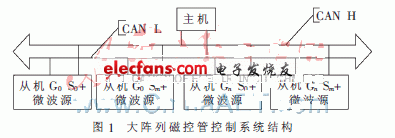
In the large array magnetron control system, there are requirements for overall control, group control and single control, so each magnetron must have a unique address. The master-slave structure is adopted, and the data exchange method is that the master sends commands to the slave, and the slave returns data in response to the master commands, and the slave can only take the initiative to alarm. In the whole system, a fixed number of slaves are a group, which belongs to distributed control. The system structure is shown in Figure 1.

Among them, G0 represents the 0th group, Gn represents the nth group; S0 represents the 0th slave, and Sm represents the mth slave.
1.1 Protocol introduction The setting of the message ID is the most important part of the application layer protocol. It involves the priority of the message, the delay, the use of message filtering, the possible formation of the communication structure and the efficiency of the use of identifiers. The system is relatively simple and independent, so the 11-bit identifier of the CAN 2.0A standard plus two data bytes is used as the ID of each frame, as shown in Table 1.

The combination of group number and slave number is used for broadcasting except for 105 types, that is, the entire system can have 105 nodes (master or slave). If you choose the commonly used Philips 82C250 as the bus transceiver, the number of CAN nodes is basically close to its limit of 110. If you need to further expand the network scale to connect more nodes, you can change the standard identifier to 29-bit expansion identifier and use the network controller to expand [6].
1.2 Protocol design The functional requirements of the magnetron control system include: first determine the number of microwave sources with normal communication and operation and whether there is address conflict between the control terminals; select all, group or single microwave sources to start or stop; real-time monitoring Various parameter values ​​of each microwave source, such as current, voltage, temperature, reflected power, and microwave leakage power; if the value of each microwave source exceeds the set threshold during operation (the threshold can be modified), or the microwave source itself appears Failure (accidental failure or permanent failure), it will alarm in real time, and the system should take corresponding measures to stop the continuous operation of related functions.
According to the above functional requirements, 8 kinds of command codes are designed:
ORD0: alarm frame (data frame), no broadcast form, the slave sends the host to read, the highest priority. In order to achieve simultaneous alarm, each bit in the function code and sub-function code represents a kind of alarm, that is, 16 kinds of alarms.
ORD1: Polling online (remote frame), the host sends ORD1 commands to each slave in turn, and the slave returns a confirmation frame after receiving, so that the master can confirm that the slave is still online.
ORD2: Calculate the communication round-trip time (remote frame). When determining that all slaves are online, calculate the average round-trip time of one frame of data between the master and slave. The round trip time will be used as a criterion to determine whether the slave response times out.
ORD3: Ask for slave data (data frame), no broadcast form, the slave sends the master to read.
ORD4: Slave address conflict detection (remote frame), each slave sends ORD4 to other slaves in its group. After receiving the ORD4, other slaves compare the address bits in the received ID with their own addresses. If they are the same, report the address conflict to the host with the ORD0 command, otherwise there is no need to respond to this message; the host itself does not process ORD4.
ORD5: broadcast command (remote frame), turn on the slave.
ORD6: broadcast command (remote frame), turn off the slave.
ORD7: modify the slave parameters (data frame), no broadcast form, the master sends the slave to execute.
ORD8 ~ ORDF are reserved command codes.
2 Realization of MWCPro protocol in large array magnetron control system
2.1 Hardware implementation By comparing various chips currently on the market, the final choice is STMicroelectronics' STM32F103VBT6 as the main chip, which is a 32-bit controller based on the ARM Cortex-M3 core. Its outstanding advantages are: advanced core structure 〠Excellent power consumption control, rich interface, high processing speed, full range of software and packaging are highly compatible, cost-effective and so on.
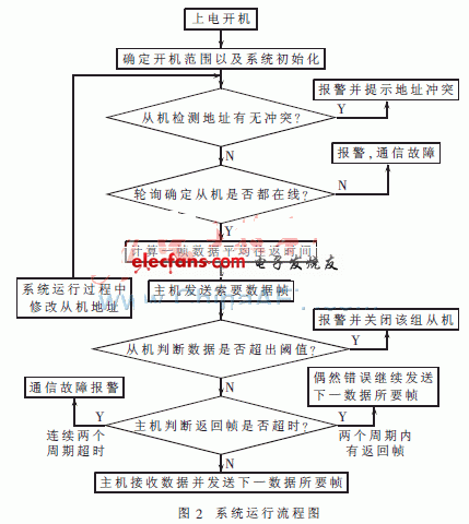
2.2 The software realizes that the entire system belongs to the master-slave control. In addition to the active alarm, the slave can only operate passively according to the requirements of the host. The software part realization process is shown in Figure 2.

3 Protocol application In practical application, there are a total of 9 microwave transmitter terminals, divided into three groups, each group of three slaves, the host computer uses a touch screen running WinCE system. The man-machine interface is shown in Figure 3. The main page includes microwave control, real-time curve, temperature curve settings, option parameters, temperature records and event records. On the microwave monitoring interface, you can see that the system is divided into manual mode and automatic mode. In manual mode, you can independently select the slave machine that needs to be turned on. You can manually switch the microwave transmitter terminal to control each section of the furnace temperature. The slave automatically starts and stops the relevant microwave transmitting terminal to control the furnace temperature of each section within the set temperature range. The system divides the furnace body into four temperature zones according to the material sintering process: preheating section, sintering section 1, sintering section 2 and slow cooling section. The system shown in Fig. 3 currently works in manual mode, starting all the slaves of group 1 and 2 of the preheating section A, sintering section I and sintering section II (the slow cooling section does not need to be heated). Through this interface, the following 6 alarms can be displayed: address conflict, furnace door, cooling water, over-current, under-current and over-temperature.
The system has the following characteristics:
(1) The time trigger and event trigger are combined to process the periodic data request frame and the non-periodic alarm information frame separately, which greatly improves the flexibility and real-time performance of the system. During the operation of the protocol, the data transmission is stable, the alarm is timely, basically meets the design requirements, and the system is practical and reliable.
(2) Compared with the previous PLC + touch screen control system, the CAN bus control method is not only simple and efficient, but also greatly reduces the cost of the control system.
The control system uses a touch screen as the host computer, but the touch screen itself does not have a CAN interface, and it needs to be converted at this time. According to the comprehensive consideration of system requirements, low cost, versatility and other factors, finally choose to use STM32-
The serial port inside F103VBT6 is used as the interface to communicate with the touch screen. It uses Modbus protocol, that is, the CAN / RS232 conversion is realized inside the chip. It can meet the system requirements without adding additional costs, and most single-chip computers have RS232 interfaces. Strong versatility. The internal conversion of CAN / RS232 can meet the system's real-time requirements during use.
The above-mentioned touch screen control system is limited to the RS232 rate when there are a large number of slaves or a large amount of information exchange on a single machine, which may cause data jam. To solve this problem, you can use the following methods: use a PC plus CAN / USB or CAN / PCI conversion interface instead of a touch screen plus CAN / RS232, because the maximum transmission rate of RS232 is only 115.2 kb / s, while the transmission rate of USB2.0 is 480 Mb / s, which is 4 266 times that of RS232; the rate of PCI can reach 1 064 Mb / s, which is 9 457 times that of RS232. Therefore, these two approaches can solve the data congestion problem well. At the same time, the number of slaves that can be directly connected to the PC is 110 (the limitation of the nature of the CAN bus). If you want to continue to expand, adding a network controller [6] can double the number of attached slaves. Even the ultra-large matrix terminal system can realize real-time control by adopting the above two schemes.
The CAN bus control system based on the MWCPro application layer protocol has fast data transmission speed and flexible configuration in practical applications, and the entire system operates stably. Although the MWCPro protocol is designed for the field of microwave control, its command codes and function codes are easy to modify and the system is easy to expand, so the protocol can also be used in other relatively simple and independent control systems, with strong practicability and universality. Sex.
Our company is specialized in supplying refrigeration and air conditioning services tools including, Vacuum Pump ,flaring tools, Tube Bender ,swagging tools, Tube Cutter ,reamer,Can Tap Valve,Manifold Gauge,Refrigerant Recovery Machine,Refrigerant Charging Scale,refrigerant leakage detector,etc.All of our tools are from famous manufacturers which have many years of experience making tools.We are focusing on the customers` feelings of the tools, which make us very strict on the quality. Our tools are beautiful and practical. Our parts have been exported to over 50 countries all over the world and are always got good comment by customers.
Service Tools
Hand Tools Flaring Tools,Service Tools Flaring Tools,Portable Vacuum Pump,Car Vacuum Pump
ZHEJIANG ICE LOONG ENVIRONMENTAL SCI-TECH CO.,LTD. , https://www.china-refrigerantgas.com