Teach you to play wireless switches to form a wireless network combat strategy
This article will clarify the role of WLAN switches and controllers through a detailed analysis of the WLAN network architecture and the functions of APs and controllers. This article will also introduce the different functions of the interface between the controller and the AP. After that, this article will explain the variables related to the second / third-tier movement in the centralized architecture, and finally will point out some common wrong views and actual situations about these architectures.
This article uses the term wireless terminal (WTP) to refer to the AP, and the term access controller (AC) to refer to the WLAN control function (whether it is deployed on a WLAN switch or an independent controller).
A WLAN switch can be connected to a WLAN access point (AP) through a wired connection (with the help of a switch port). They can also connect to the corporate network through their other switch ports. These switches are "gateways" connected to the corporate wired network-all data frames from the WLAN client must be sent to the corporate network through the WLAN switch.
To understand the function of a WLAN switch and its application in a network, you first need to understand the network architecture of the WLAN and the functions of the access point. We can think of WLAN switches as control devices and APs as wireless terminals.
Main structure of WLAN network
There are three main WLAN network architectures:
1. Autonomous architecture
2. Centralized architecture
3. Distributed architecture
The following sections will introduce these three architectures in depth.
Autonomous architecture
In an autonomous architecture, WTP fully deploys and terminates 802.11 functions. Therefore, all data frames on the wired LAN are 802.3 frames. Each WTP can be used as a separate network entity on the network for independent management. Access points in such networks are often referred to as "fat APs" (see Figure 1).
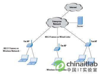
Figure 1. Fat AP in an autonomous WLAN network
In the early days of WLAN deployment, most APs are autonomous APs, which can be managed as independent network entities. In the past few years, the centralized architecture using AC and WTP (see below for details) has begun to receive more and more attention. The main advantage of the centralized architecture is that for multiple WTPs in an enterprise, it can provide a structured and hierarchical control mode for network administrators.
Centralized architecture
The centralized architecture is a hierarchical architecture that includes a WLAN controller that is responsible for configuring, controlling, and managing multiple WTPs. The WLAN controller is also called an access controller (AC). 802.11 functions are jointly undertaken by WTP and AC. Compared with the autonomous architecture, the function of WTP in this mode has weakened, so they are also called "thin AP". Some functions on the AP are variable. For details, see the introduction in the next section (see Figure 2).
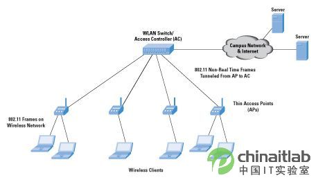
Figure 2 Thin AP in a centralized WLAN network architecture
Distributed architecture
In a distributed architecture, different WTPs are wired or wirelessly connected to establish a distributed network with other WTPs. A mesh network composed of WTP is a typical example of this architecture. WTP in a mesh network can be connected to 802.11 links or wired 802.3 links. This architecture is commonly used in urban networks and other deployments that require "outdoor" components. Distributed architecture is beyond the scope of this article.
WTP function-fat, thin and moderate AP
To understand autonomous and centralized architectures, you first need to analyze the functions performed by the AP. We start with the fat AP, which forms the core of the autonomous architecture. Later we will introduce the thin AP, which is an important part of the centralized architecture based on WLAN switches or controllers. This article will then introduce the function of a new component called "Moderate AP". It is an AP specifically optimized for a centralized architecture.
Fat access point
Figure 1 shows an autonomous network using fat access points. An AP is an addressable node in the network and has its own IP address on its interface. It can forward traffic between wired and wireless interfaces. It can also have multiple wired interfaces to forward traffic between different wired interfaces-similar to a Layer 2 or Layer 3 switch. The connection to the corporate wired network can be achieved through a Layer 2 or Layer 3 network.
It is worth noting that fat APs will not "return" traffic to other devices through the tunnel. This feature is very important, this article will also mention this when introducing other AP types. In addition, fat APs can provide "router-like" functions, such as the Dynamic Host Configuration Protocol (DHCP) server function.
The management of the AP is performed through a protocol (such as Simple Network Management Protocol [SNMP], or Hypertext Transfer Protocol [HTTP] for Web management) and a command line interface. In order to manage multiple APs, the network administrator must connect to each AP through one of these management mechanisms. Each AP appears as a separate node on the network topology diagram. Any aggregation of nodes for management and control must be done at the network management system (NMS) level, which includes the development of an NMS application.
Fat AP also enhances a variety of functions, such as an access control list (ACL) that permits filtering of traffic from specific WLAN clients. Another important function of these devices is the configuration and implementation of functions related to quality of service (QoS). For example, traffic from a particular mobile base station may need to have higher priority than other traffic. Or, you may need to insert and implement IEEE 802.1p priority, or differential service code points (DSCP), for traffic from mobile base stations. In short, because these APs can provide many functions of switches or routers, they can act as switches or routers to a certain extent.
The disadvantage of this AP lies in its complexity. Fat APs are usually built on powerful hardware and require complex software. Because of their complexity, the installation and maintenance costs of these devices are high. Nevertheless, these devices can also play a role in small networks.
Some fat APs use a controller at the back end for control and management functions. These controllers will form a slightly simplified version of the fat AP-the so-called "moderate AP", which will be described in detail below.
Thin access point
As the name suggests, the purpose of thin AP is to reduce the complexity of AP. An important reason for simplifying it is the location of the AP. Many companies have adopted high-density installation methods for APs (because they are distributed in areas that are difficult to access) to provide the best RF connection for each base station. In special environments such as warehouses, this phenomenon is more pronounced. For these reasons, network managers want to install the AP only once without complicated maintenance.
Thin APs are often called "smart antennas", and their main function is to receive and send wireless traffic. They will send wireless data frames back to a controller, and then process these data frames, and then exchange to wired WLAN (see Figure 2).
This AP uses a (usually encrypted) tunnel to send wireless traffic back to the controller. The most basic thin AP does not even perform WLAN encryption, such as wire equivalent encryption (WEP) or WiFi protected access (WPA / WPA2). This encryption is done by the controller-the AP is only responsible for sending or receiving encrypted wireless data frames, thereby maintaining the simplicity of the AP and avoiding the need to upgrade its hardware or software.
The advent of WPA2 makes encryption on the controller a very urgent task. Although WPA is compatible with WEP in hardware and only requires a firmware upgrade, WPA2 is not backward compatible. The network administrator does not need to replace the AP of the entire enterprise, but only needs to send wireless traffic to the controller capable of WPA2 decryption, and then the data frame will be sent to the wired LAN.
The protocol for transferring control and data traffic between the AP and the controller is dedicated. Moreover, it is impossible to manage the AP as a unified entity at the second / third layer-it may be managed by the controller, and the NMS can communicate with the controller through HTTP, SNMP, or CLI / Telnet. One controller can manage and control multiple APs, which means that the controller should be based on powerful hardware and usually be able to perform switching and routing functions. Another important requirement is that the connection and tunnel between the AP and AC should ensure that the packet delay between these two entities is kept at a very low level.
For thin APs, QoS execution and ACL-based filtering are handled by the controller-this does not cause problems, because all data frames from the AP must be transmitted via the controller in any case. The centralized control functions of ACL and QoS are not uncommon-networks that use fat APs also use this method. This installation uses the controller as a gateway to manage the traffic from the AP to the wired network. However, the controller function of the thin AP adopts a new way, especially in the data plane and the forwarding function. The controller function is integrated into an Ethernet switch connecting wireless and wired LANs-this gave birth to a series of devices called "WLAN switches".
In this case, the wireless MAC architecture is called the remote MAC architecture. The entire set of 802.11 MAC functions are transferred to the WLAN controller, including MAC functions that are sensitive to delay.
Moderate access point
Moderate APs are also getting more and more popular because they combine the advantages of fat APs and thin APs. A moderate AP can use the AC for actual key exchange while providing wireless encryption. This approach is used for new APs that use the latest wireless chipsets that support WPA2. Management and policy functions are performed by controllers that are tunneled to multiple APs.
Moreover, the moderate AP also provides some additional functions, such as a DHCP relay function that allows the base station to obtain an IP address through DHCP. In addition, moderate APs can perform VLAN tagging based on service set identifiers (SSIDs), allowing clients to associate with APs (when APs support multiple SSIDs).
Moderate AP supports two types of MAC deployment, namely local MAC and split MAC architecture. Local MAC means that all wireless MAC functions are performed at the AP. The complete 802.11 MAC functions (including management and control frame processing) are performed by the AP. These functions include some time-sensitive functions (also known as real-time MAC functions).
The split MAC architecture distributes MAC functions between the AP and the controller. Real-time MAC functions include beacon generation, detection signal transmission and response, control frame processing (such as Request to Send and Clear to Send, namely RTS and CTS), and retransmission. Non-real-time functions include authentication and de-authentication; association and re-association; bridging between Ethernet and wireless LAN; and segmentation.
Products from different vendors have different ways of assigning functions between APs and controllers. In some cases, even their definition of real time is different. A common moderate AP implementation includes the AP's local MAC, as well as the AP's management and control functions.
Access controller and control functions
The next key component of the centralized WLAN architecture is the access controller (AC). In the following, we think that the controller function is deployed on a WLAN switch, and the function is called AC. We also use the term "WTP" to refer to AP (including fat, thin, or moderate).
The IETF Wireless Access Point Control and Configuration (CAPWAP) working group is defining the interface and protocol between the AP and the WTP it controls. In this section, the interface between AC and WTP will be introduced in detail using the CAPWAP framework. [3, 4, 5]
Figure 3 shows an enterprise network with multiple ACs and WTPs. WTP can be connected to AC through a Layer 2 (switching) or Layer 3 (routing) network. The interface between WTP and AC is responsible for the following functions:
* Discover and select an AC through WTP
* Download firmware to WTP via AC-after startup and WTP trigger
* Function negotiation between WTP and AC
* Two-way authentication between WTP and AC
* Configuration, status and statistical data exchange between WTP and AC
* QoS mapping between wired and wireless network segments
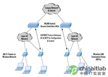
Figure 3: Centralized WLAN architecture using multiple AC, WTP and CAPWAP protocols
Campus Network and Internet
WLAN switch / access controller (AC)
CAPWAP protocol for configuration and control between AC and WTP in Layer 2 / Layer 3 networks
Layer 2 / Layer 3 network
802.11 frame wireless LAN termination point (WTP) on wireless network
In addition, although CAPWAP does not clearly define all the details, the AC can perform functions such as radio resource management (RRM) and rogue AP detection by configuring and monitoring different access points in the area it controls. The scope of these features will vary depending on the vendor's deployment method. Another important function provided by AC is mobility management. The following chapters will provide more details about these functions based on CAPWAP. Please note that as of this writing, the IETF is still working on a CAPWAP protocol based on the Cisco Lightweight Access Point Protocol (LWAPP) (March 2006).
AC discovery and selection
WTP can discover available ACs through discovery request messages. One or more ACs (depending on the network topology) will respond to these request messages. The communication between AC and WTP is performed through User Datagram Protocol (UDP). WTP will decide which AC to connect to, and then try to establish a secure session with that AC. Subsequent CAWAP packets will be sent through the secure session.
Then, AC and WTP will exchange configuration. These exchanges include:
* IEEE SSID
* Security parameters (for WEP, WPA and WPA2)
* Broadcast data rate (11 or 54Mbps)
* Need to use wireless channel
CAPWAP function
CAPWAP control messages include the following message types:
* Find
* WTP configuration-used to publish a specific configuration to WTP, and obtain statistical information from WTP; statistical information includes the following information:
* The number of segmented data frames, and the number of multicast data frames sent and received
* Send retry times, excessive retry times (failure times)
* The number of successful and failed sending requests (RTS)
* Number of erroneous data frames: repeated data frames, error confirmation, decryption errors, frame check sequence (FCS) error numbers, etc.
Configurations include beacon period, maximum transmit power level, orthogonal frequency division multiplexing (OFDM) control, antenna control, support rate, QoS, and encryption.
* Mobile session management-release specific mobile strategies to WTP
The AC can add policy information about a specific mobile device, including the security parameters that WTP should use for that mobile device. It may include whether WTP should forward or drop traffic for the mobile device.
* Firmware management-used to publish a specific firmware image to WTP.
AC and WTP interaction
WTP can provide a variety of information, such as hardware, software or boot version; maximum number of wireless frequency bands; currently used wireless frequency bands; encryption function; wireless frequency band type (802.11b / g / a / n); MAC type (local, separate or Both); tunnel mode; and the frame type between AC and WTP (for example, local bridge or built-in bridge-that is, all user payloads are encapsulated into original wireless frames).
The AC information includes the hardware or software version, the number of mobile base stations currently associated with the AC, the number of WTP currently connected to the AC, the maximum number of all these devices, the security parameters (authentication certificate) between AC and WTP, control IPv4 or IPv6 address, etc.
Because WTP is a "moderate AP", they can also configure an IP address from the AC. Another parameter that can be configured is the MAC address level ACL.
You can restart (reset) WTP through AC at any time. WTP can independently request a new image through a mirror data request, and then receive the mirror data response and the mirror data itself.
When WTP determines that important information needs to be sent to the AC, WTP will issue an event. This information may include data transmission messages used to send debugging information from WTP to AC.
Wireless resource management
Radio resource management is a general vocabulary used to describe the control and configuration of wireless frequency bands on the AP. Types of control include reducing and increasing the intensity automatically or based on user input—for example, if two WTPs controlled by an AC interfere with each other, the AC sends a signal to one of the APs to reduce its intensity. It can also perform this operation according to the user's configuration.
Some WTPs are also set to be able to act as "wireless monitors"; that is, they can monitor channels when they are not sending data. There is currently some controversy about the effectiveness of this WTP usage model-some vendors use specialized wireless monitors instead of letting their WTP do double duty. In the case of using a dedicated wireless monitor, you can scan and monitor all channels without worrying about reducing the service quality of the customer base station.
The wireless monitor can forward all information related to other access points to the AC. The AC can determine whether the information is for a valid WTP (that is, it does exist on the network and has been registered with the AC), or is a "malicious" Access Point. If targeting a malicious access point, the AC can perform multiple steps to prevent clients from connecting to the AP—for example, it can instruct the wireless monitor to “block†the malicious AP by increasing the transmit power on the same channel .
Mobile management
Mobility management can take two forms-Layer 2 and Layer 3 mobility. Suppose a client moves from one WTP to another WTP-this may happen when a user who uses a laptop computer moves between two conference rooms in the same building. The client base station will re-associate with the new WTP and then perform identity verification. Please note that before it “establishes†the association with the new AP, its association with the original AP will be “disconnectedâ€; therefore, the handover in the WLAN is called “disconnect first, then establishâ€. Although this method may cause potential traffic interruption (and retransmission), it is still better than "establish first, then interrupt" (for cellular network communication), which can keep the client wireless connection simple and cheap.
One way to understand Layer 2 and Layer 3 movement is to treat Layer 2 movement as movement between APs controlled by the same AC (that is, belonging to the same Layer 3 network), while Layer 3 movement It is the movement between APs controlled by different ACs.
Layer 2 mobile network management
Layer 2 mobility means that when the base station moves from one WTP to another, the IP addressing capability will not be affected, which means that all APs are located on the same layer 2 network, ie they are all connected to the same AC (See Figure 4). In order to prevent the loss of data sent by the second layer client, the WLAN switch must now forward the client data to the new WTP. After the client is associated, the new WTP will send an Ethernet frame to the AC and use the client ’s MAC address as source address. The switch can now associate the client's MAC address to the port connected to the new WTP.
Although this process is applicable to the layer 2 (switched network) connection between the AP and AC, when using a tunnel connection between them, a slightly different method is required. After receiving the MAC frame from the new WTP, the AC will transfer the client's mapping to a different tunnel (that is, a virtual port).
Another issue that needs to be considered for layer 2 switching is WTP data caching. Under normal circumstances, the switch or AC will not realize the necessity of handover before receiving information from the new WTP. However, if WTP has enhanced statistical information, it can determine that a particular client has moved out of the original WTP, thereby stopping forwarding data to the original WTP. These statistics may include: Carrier Sense Multiple Access / Collision Avoidance (CSMA / CA) MAC layer protocol maximum retry times on the wireless link. The switch does not need to cache data, because it is not clear when to switch to the new WTP. This method helps to avoid wasting traffic on the link between the original WTP and AC.
With the help of fat APs, some suppliers have adopted a different approach to solve this problem. According to this method, the AP buffers the traffic until it receives a data frame from the switch indicating that the client has transferred to another switch port. These APs can send the buffered traffic to the switch, and then the switch forwards the traffic to the new WTP. Because our purpose is to reduce the complexity of WTP, this method is obviously not the preferred method in the centralized AC + WTP architecture.
Another important feature of Layer 2 roaming is the need for pre-identification on the new WTP. Through 802.11i, the client can pre-identify the adjacent WTP, so that roaming to different WTP does not need to go through a lengthy authentication process, that is, there is no need to send a dual master key (PMK) to the new WTP. (But still need to get the double transition key [PTK].)
When the AC maintains a PMK for a particular client (through interaction with a RADIUS server), the process will automatically proceed-that is, the AC will send the PMK for the client to a new WTP. The encryption of 802.11 frames still uses the new PTK , Completed by the original and new WTP.
Layer 3 mobile network management
Layer 3 mobility requires the client to maintain the same IP address when roaming between multiple APs. This usually happens when the customer has published its IP address to multiple nodes. This situation often occurs in peer-to-peer communication, that is, when a mobile base station needs to act as a server for a certain function. Ideally, no matter when a mobile node moves to a new layer 3 network, other nodes communicating with the mobile node do not need to change their configuration.
Mobile IP solves the problems of Layer 3 mobile [6]. We are not going to discuss the specific details of Mobile IP here, but it should be pointed out that it contains three different components. The local agent (HA) on the client's local network is responsible for the client's address. All packets sent to the client's (unchanged) IP address are sent to the local agent. If the client is on the local network, HA will directly forward the packet to the client. If it is located on an external network or interviewed network, HA will forward the packet to an external agent (FA) located on the interviewed network.
For this, it must set up a tunnel pointing to the FA-this is usually a General Routing Encapsulation (GRE) or IP-in-IP tunnel.
After separating the original packet from the tunnel, the FA is responsible for forwarding the packet to the client. This is only a rough description, in fact, it involves a lot of other steps. In a wireless local area network, the key to achieving Layer 3 client movement is the location of the mobile IP terminal. Some customer base stations include a software stack for MIP clients.
This client-side MIP (CMIP) software will:
* Separate the MIP header in the packet
* Insert a new header to convince the client's high-level application that the packet is sent to the client's IP address on the external network
*
The CMIP method is the recommended method for deploying MIP. But its shortcoming is that you must add a MIP client for each mobile base station in the network-when there are a large number of mobile base stations, this configuration may be quite cumbersome.
The centralized AC + WTP architecture provides a way to solve this problem. Some AC / WLAN switch vendors have deployed MIP functions on the AC so that clients do not need to make changes. Some deployments call this a proxy MIP function.
The AC can act as an FA, terminate the tunnel from the HA, and when forwarding packets to the client, resolve the packets addressed to the client's address on the visited network. When the client sends Layer 3 packets, it will send these packets through the AC, and then modify the header of the source IP address, and send these packets to the HA through the tunnel. This process is called "reverse tunnel" (see Figure 4 ).
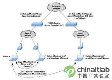
Figure 4 Layer 2 and Layer 3 mobility in a centralized WLAN network architecture
Corporate network
AC acts as a mobile IP local agent for base station A? ?
AC acts as a mobile IP external agent (FA) and proxy MIP client for base station A
WLAN switch / access controller (AC)
Layer 2 network Layer 2 network
Base station A layer 2 mobile client transfers to AP on the same AC
Base station A roams to an AP on the same layer 3 network
Base station A roams to an AP on a different layer 3 network
Layer 3 mobility-when a mobile base station moves from an AP to a different AC
When considering a large enterprise network topology that includes multiple ACs and APs, you can consider establishing a MIP tunnel between different ACs. (That is, they act as external agents for a group of users, and local agents for another group of users) From a scalability perspective, the AC must have sufficient processing power and switching capacity (exchange the tunnel from AP to AC to AC Between the tunnel).
WLAN switches and centralized architecture-common misconceptions The previous sections introduced different aspects of the centralized AC + WTP architecture, as well as some noteworthy deployment elements. This section will introduce some common misconceptions about these architectures and their deployment, the purpose is to better examine this area that is still in the development stage.
* Myth 1: The AC needs to perform a switching function-hence the name WLAN switch.
AC does not need to meet such requirements. In fact, the earliest ACs were all additional devices (such as PCs running Linux). Control functions are an important part of deployment-switching is often used to speed up the forwarding of traffic sent and received by the AP.
* Myth 2: The malicious WTP detection is a standard function of AC.
This feature is required in some deployments, but this is not a necessary "standard". One reason is that various vendors have adopted different approaches in this regard (for example, the algorithms they use to classify WTP as malicious WTP). Another reason is that the AC must rely on APs or wireless monitors. This dependency will vary depending on the deployment method.
* Myth 3: The boundary between fat, thin and moderate AP is very clear.
There are many different ways to implement AP (and AC) functions, so this view is not necessarily correct. For an example of a classification (snapshot) of WTP and AC implementation, please refer to RFC 4118 [4].
* Myth 4: Layer 2 and Layer 3 mobility are standard functions of the AC + WTP architecture.
This view is actually wrong. The proxy MIP deployed for Layer 3 mobile is just a step in this direction, and most AC vendors rely on dedicated mechanisms to provide AC-AC communication and Layer 3 mobile functions.
* Myth 5: Security functions (such as firewalls, intrusion detection, etc.) are not AC functions.
Some vendors have refuted this view: they added these features to their AC. This is one of the ways for suppliers to establish their own characteristics.
Summary This article lists the main features of the CAPWAP control function, as well as some issues related to Layer 2 and Layer 3 mobility when deploying the AC + WTP architecture. Although the IETF is developing standard protocols for this emerging field, suppliers still have enough room to establish their own characteristics. This article describes the functions and deployment of WLAN switches by introducing in detail the architecture that relies on a centralized controller to manage a group of wireless terminals.
Catalog of Flashing LED.
We are flashing LED manufacturers from China.
Five Years warranty.
All of our product are meet with Reach, CE, RoSH, SGS, EN62471 standards.
We supply single flashing LED Lights, colorful fast flashing LED lights, colorful slowlly flashing LED lights, full color flashing LED lights and so on.
The shape can be SMD Falshing LED and Through-Hole Flashing LED. At the same time.
It is compatible with addressable LED: Like WS2812RGB, SK6812RGB, SK6812RGBW, SK9822RGB, APA102RGB ect.


We have 100% product testing system and excellent after-sales service and technical support. Look forward to working with you.
Flashing LED
Flashing LED, Silicone Flashing LED, Remote Controlled Flashing LED, Sound Sensor Flashing LED
Shenzhen Best LED Opto-electronic Co.,Ltd , https://www.bestsmd.com