Recently, due to the prevalence of environmental protection awareness and animal protectionism, high-quality artificial leather has been widely welcomed in the international market. Therefore, the tannery machinery has gained new development in recent years. Especially for the wet leather production line, in order to improve the accuracy and reliability of the system, most manufacturers currently abandon the traditional implementation of synchronous controllers and temperature controllers. Instead, they have entered the pattern of PLC plus touch screen, or industrial computer plus PLC control. The production line has a length of 100-150M. There are also 60-70 analog signals.
Therefore, in order to reduce costs and increase the reliability of the system. We use PCC (Computer Control Center), add CAN bus distribution acquisition module, and touch screen to form the automatic control system of wet leather production line.
1. Overview of PCC
B & R's PCC controller uses a time-sharing multi-tasking operating system, so the control requirements can be divided into multiple tasks (tasks) and executed simultaneously in a scan cycle; the programming environment Automatoin Studio under Windows supports standard C, Basic, ladder diagrams , Instruction list, sequence structure diagram and other six standard development languages; according to the need to use multiple languages ​​for programming in the same project. At the same time, the programming environment contains a wealth of function libraries and function blocks (FuncTIonblock), which greatly reduces the workload of developers. In the development of PCC software in this set of control system, we mainly adopted the programming method mainly in C language and supplemented by ladder diagram.
2. Overview of CAN bus
CAN, the full name is "Controller Area Network", that is, the controller area network, is one of the most widely used field buses in the world. Initially, CAN was designed to communicate as a microcontroller in the automotive environment, exchanging information between ECUs in the vehicle to form an automotive electronic control network. For example: CAN control devices are embedded in engine management systems, gearbox controllers, instrumentation equipment, and electronic backbone systems. CAN is a multi-master serial communication bus. The basic design specifications require a high bit rate, high electromagnetic interference resistance, and can detect any errors that occur. When the signal transmission distance reaches 10Km, CAN can still provide a data transmission rate of up to 50Kbit / s.
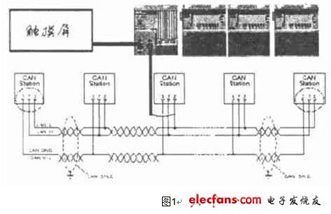
3. General introduction of the system
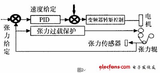
The system consists of three parts: touch control screen, PCC and CAN bus module. See Figure 1 for the specific structure. Among them, the touch screen mainly completes the setting of process parameters, such as the temperature of the roller, the speed of the system, etc .; displays the tension of each roller and the historical parameters, and shows the operating status of the system. Including inverter current, fault code, etc. The RS232 port of the touch screen establishes point-to-point communication with the RS232 of PCC. The original FARAME-DRIVE function is owned by PCC. Therefore, it can communicate with almost all RS232 devices. PCC is the core of the production process control. The main function is to complete the scanning of each CAN bus module to obtain the temperature and tension roll position signals on site. According to the requirements of process parameters, various PID operations are performed to output control signals to the CAV bus output function block. The block diagram of its system structure is shown in Figure 2.
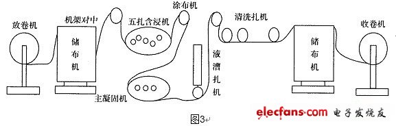
4. Principle of synchronous control
(1) The transmission circuit diagram of the system: the unwinding and winding of the system are controlled independently by the torque motor. The speed of the entire system follows the movement of the main coagulator. The main coagulator is driven by a 5.7KW vector inverter. The given signal is taken from the setting of the touch screen. 31 other main frequency machines are dragged by other binding machines. The speed of each binding machine is guaranteed to be synchronized with the main coagulation machine. Its structural block diagram is shown in Figure 3. Under the condition of ensuring constant tension, it can ensure the synchronization of the system speed. In order to speed up the adjustment time, the feedforward control quantity speed setting is added to reduce the tension fluctuation during the starting and speed up and down of the system. Once tension overload occurs during the tension control process, the PCC output control valve lifts the pressure roller. After the tension returns to normal, the pressure roller is automatically pressed again, and its control strategy adopts double-position control.
(2) Temperature control: The temperature uses C language to use PID function, which can control infinite temperature regulation. In this system, 8 to 10 channels of temperature control are generally controlled. Because it uses C language, it can dynamically define the current number of temperature control, ordinary temperature control table or PID regulator is difficult to accurately temperature control; and B & R company intelligent temperature PID software can automatically calculate the different temperature control required PID parameters make the temperature control accurate to ± 1 ℃.
5. The characteristics of the PCC's CAN bus and the communication with the lower CAN module
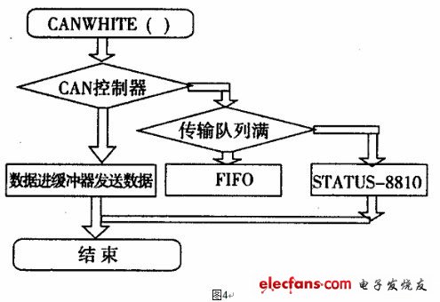
(1) Use of PCC's CAN bus
The CAN frame of PCC can be read and written with up to 8 bytes of information. This part is realized by calling the CAN function library. These include CONOPEN, CANWRITE, CANREAD, and SANTAB and CANRWTAB. The CANOPEN function includes completing the initialization of the CAN bus. It should be noted that the initialization of the CAN bus must be included in the initialization routine INTI SP. CANOPEN (1, BAND-RATE, COB-ANT, ADR (ERRO-ADR), 0., 0 US-IDENT, STAFUS) where BAND-rate = 25, which means that the baud power is 250K. US-IDENT is to call CAN The CAN ID obtained by the initialization to the PCC will be used in the reading and writing process of the CAN bus. The CAN bus write information uses the CAN2WRITE function in the process with higher priority, and its function parameters are defined as follows: CANWRITE (BAND-RATE, COB-ANT, ADR ERRO-ADR, 0, 0, US-IDENT, STATUS), enable = 1, us-idenf is the us-idenf established during CANopen () initialization. CAN-id is the ID of the CAN data frame related to the data target CAN module. DATE-ADR is the first address of the sending data module. Date-iog is the length of the data sent. The maximum value is 8. If CAN-id is used as the frame address data to be successfully sent, status = 0, otherwise status = error code. The process of sending data is as follows:

Shenzhen Dianjiang Engineering Co. LTD , https://www.isourceled.com