1 Introduction
Due to the system integration characteristics of the CAN bus, the application range of the CAN bus technology based on the car body control system has far exceeded the field of automotive control and expanded to various other measurement and control fields such as the machinery industry, household appliances and sensors, and is recognized as important by the international community. Industrial fieldbus. As the object of motion control, the stepper motor as a mechanical actuator that converts discrete electrical pulse signals into angular displacement has the advantages of simple structure, low cost, high positioning accuracy and no error accumulation. It has been widely used in various Automatic control system. With the development of microcomputers and microelectronics technology, this performance of stepper motors is bound to be more widely used. Therefore, it has very obvious practical significance for the research of stepping motor control of CAN bus.
2 Overall system design plan
The system can be used as a host computer to send commands through a PC, and can be connected to the CAN bus through a bus-can interface conversion module. Each node is a module with a CAN bus data transmission and reception function controlled by a single-chip microcomputer to control the stepper motor driver and motor terminal. In the application layer of the PC, the data is sent from the usb interface to the single-chip microcomputer on the usb-can interface conversion module of the universal device interface chip ch372 based on the usb bus according to the format specified in advance. After the single-chip microcomputer processes the data, it transmits the data to each connected On the can bus of the node of the stepper motor driver, the control module of each node processes according to the received data information to realize the speed, forward and reverse and stroke control of the stepper motor. Figure 1 shows the system plan of this design.
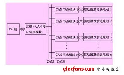
Figure 1 System overall plan
3 Hardware design
The hardware of the system includes the design of usb-can interface module and can node receiving module circuit.
3.1 Design of usb-can interface module circuit
The bus-can interface module is mainly composed of 51 single-chip microcomputer, ch372, sja1000 and 82c250. The host sends data to the single-chip microcomputer through ch372, and the single-chip microcomputer sends the data to the can bus through sja1000. Figure 2 shows the main components and their connections from the USB port of the PC to the CAN bus. The vdd and vcc in Figure 2 and Figure 3 are + 5v DC power supply, ch372 supports two power supplies, + 5v and + 3.3v, + 5v is used in this design, which can be obtained directly from the USB port, simplifying the circuit design. The ch372 and sja1000 connected with the single chip realize the non-interference read and write process through the chip selection signal, and complete their respective tasks.
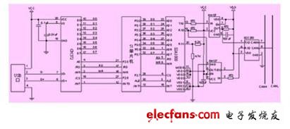
Figure 2 Schematic diagram of usb-can interface conversion module
To achieve its function, the can control must have peripheral expansion interfaces to form a complete can communication system. This design uses the pca82c250 device as the interface between the sja1000 of the can controller and the physical bus to provide the differential transmission and reception capabilities of the bus. The signals of the canh and canh lines, and pass the processed signals to the can receiving area of ​​the control unit. In order to protect the chip and improve the anti-interference ability, a high-speed photoelectric isolator 6n137 is added between the controllers sja1000 and 82c250. The 120 ohm matching resistance must be connected at both ends of the CAN bus network, which can greatly improve the anti-interference and reliability of communication.
3.2 Design of can node module circuit
The circuit design of the can interface part of the can node module and the can interface part of the usb-can interface conversion module are the same, as shown in FIG. 3. After processing the received data, the single-chip microcomputer displays from p1.0 and p1.1, and outputs the motor rotation direction signal and the pwm pulse signal with a certain frequency and a certain number to the motor driver to realize the control of the motor. In order to improve the anti-interference ability, add the optical isolator tlp5621, because the output digital signal frequency is not very high, the conversion time of tlp5621 has met the requirements. For the safety of the motor operation, two mechanical emergency stop buttons can be set at appropriate locations around the motor load. When the load fails, the button is pressed to notify the microcontroller to stop the pwm output to realize the motor fault emergency stop.
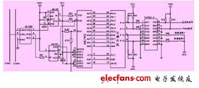
Figure 3 Schematic diagram of the can node module circuit
China Restaurant Pos Software ,All In One Pos Systems , Smart Pos Machine Manufacturer
THE Restaurant Pos System DESIGNED TO HELP YOU GROW
Gmaii Food Beverage Pos System`s tablet point of sale system speeds up, simplifies, and automates restaurant operations so you can focus on what`s important.
Gmaii Food Beverage Pos System Register at Press Street
Gmaii Food Beverage Pos System`s Restaurant Pos System at Your Service.
Everything about Gmaii Food Beverage Pos System`s system is designed to help you turn, burn, and earn more efficiently than ever before.
Front and Back of House
Tableside Ordering
Mobile Business Insights
Staff Management
Reporting and Analytics
Customer Support
Customer Loyalty
Customizable Hardware
Integrated payment processing
Online Ordering
Integrated Accounting
Multi-Location Management
Food Beverage Pos System
Restaurant Pos Software ,All In One Pos Systems ,Smart Pos Machine ,Best Pos System For Restaurant
Shenzhen Gmaii Technology Limited , https://www.gmaiipos.com