Wearable technology has rapidly become a staple in many people's everyday lives and work routines. These devices are used for a variety of tasks, with the most common being health monitoring and scheduling management. With the rapid pace of innovation in this field, ABI Research predicts that the compound annual growth rate for wearable devices will reach 56.1%, with total shipments expected to hit 487 million units by 2018. For aging baby boomers, this timing is particularly advantageous since precise medical monitoring can help address serious health issues. As user expectations for device performance continue to grow, system designers must create smaller, more efficient, and cost-effective solutions to make wearables accessible to more individuals.
Popular wearable devices like the Samsung Gear and Apple Watch offer connectivity, high-quality displays, and numerous features, while others, such as the Fitbit Flex and Jawbone UP4, focus on health monitoring. One of the biggest concerns among consumers regarding these devices is their battery life. How long can they last on a single charge? Battery longevity is a critical factor in determining which wearable device to buy.
This article delves into the system module design of a typical wearable device and examines how a boost-buck regulator can enhance power efficiency, thereby extending battery life. Engineers designing wearable systems will gain insights into how a new regulator can use adaptive current-limited pulse-frequency modulation (PFM) and forced-bypass mode to provide seamless transitions between buck and boost modes, preventing signal spikes in applications. High light load efficiency and quick transient responses are crucial in these applications.
Wearable Device Architecture
A typical wearable device architecture includes components such as microprocessors, memory, displays, sensors, communication ICs, and battery charging blocks. Depending on the system’s application, at least three DC-DC converters and three to five low dropout (LDO) linear regulators are necessary. Figure 1 illustrates a standard power system for a basic wearable device.
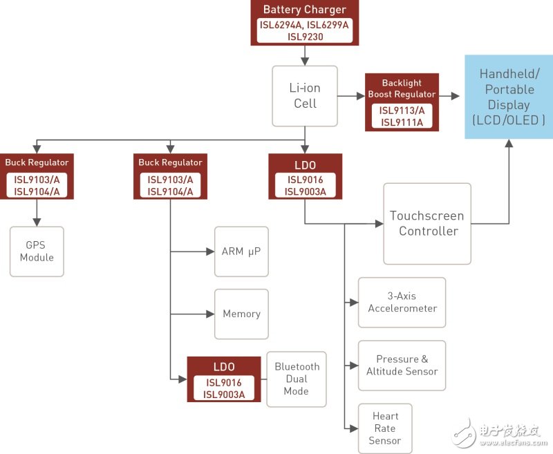
**Figure 1: Block diagram of a typical power solution for a wearable device**
Battery Charger: Battery Charger
Li-ion Cell: Lithium-ion battery
Backlight Boost Regulator: Backlight boost regulator
Handheld/Portable Display: Handheld/portable display
Buck Regulator: Buck Regulator
GPS Module: GPS module
Memory: Memory
Bluetooth Dual Mode: Bluetooth Dual Mode
Touchscreen Controller: Touchscreen controller
3-Axis Accelerometer: 3-axis accelerometer
Pressure & Altitude Sensor: Pressure and altitude sensors
Heart Rate Sensor: Heart rate sensor
First, let’s explore how boost-buck regulators add value to wearable systems. For applications needing an input voltage of around 3.3V to 3.6V, these regulators can efficiently utilize a broad range of new chemical cells with voltage ranges from 4.375V to 2.5V. The boost-buck regulator operates in pure boost mode when the battery voltage (Vbat) is between 2.5V and 3V. It switches to boost-buck mode when Vin is between 3V and 3.9V, and finally enters pure buck mode when Vbat is between 3.9V and 4.5V.
Using a Step-Up Converter as a Pre-Regulator
Applications like Wi-Fi and display modules are often powered by an LDO. Directly powering these peripherals from the battery results in significant power loss due to the inefficiency of the LDO. By using a step-up converter as a pre-regulator for the LDO, system efficiency improves. Additionally, this configuration ensures the LDO consistently experiences a constant input voltage (boost-buck output) power loss, avoiding excessive heat generation from direct battery power. As wearable devices incorporate more features, there’s a growing demand for faster processing speeds, necessitating more efficient power management. When multiple applications run simultaneously, short-time high current pulses can cause the local node voltage to dip below the recommended input range, leading to device shutdown. This issue can be mitigated by using boost-buck converters as pre-regulators for devices like LCDs and those powered by LDOs.
Extending Battery Life
The ISL9120 step-up regulator offers excellent efficiency under both low and high load conditions. As shown in Figure 2, its adaptive pulse frequency modulation (PFM) mode achieves efficiencies as high as 98% at higher loads and over 86% at lower loads. This reduces power consumption and heat generation, extending battery life and saving board space by eliminating the need for external heatsinks. To optimize efficiency across the output current range, the ISL9120 employs a multi-level current-limiting scheme divided into 32 levels ranging from 350mA to 2A.
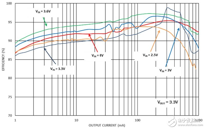
**Figure 2: ISL9120 Boost-Buck Regulator Efficiency Graph**
As illustrated in Figure 3, the transition between current limit levels is determined by the number of pulses in a PFM burst. At a given peak current limit level, the number of pulses increases with output current. When the number of pulses reaches the upper threshold of the current limit, the current limit transitions to the next higher level. Conversely, if the number of pulses falls below the lower threshold, the device transitions to the next lower level of the peak current limit. At the highest current limit, the current limit stops increasing. The ISL9120 also supports forced bypass mode, where no output adjustment is required. In system standby mode, it achieves ultra-low quiescent current consumption of less than 0.5μA. For instance, when an LDO is powered and in standby mode with near-zero output current, putting the boost-buck regulator into bypass mode has minimal impact on the LDO while saving 41μA of quiescent current.
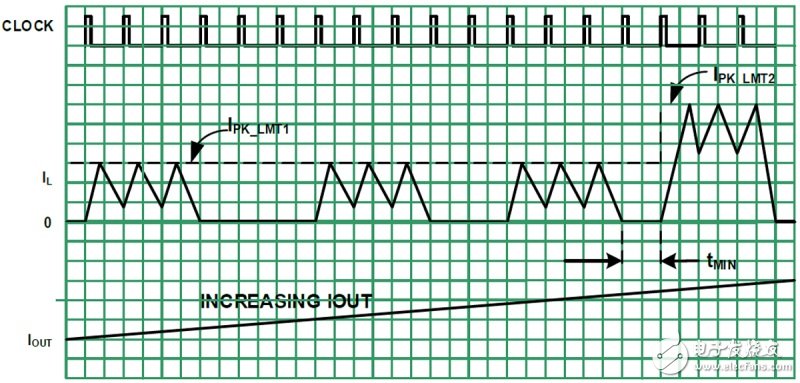
**Figure 3: Adaptive current scheme provides smooth transition from buck to boost**
Increasing Iout: Iout is rising
Boost-Buck Application Example
A closer look at Figure 1 reveals the advantages of using boost-buck regulators in wearable device applications. Heart rate monitor sensing systems typically require approximately 3.3V input voltage, and system designers often recommend using 2 to 3 LEDs for accurate monitoring, as this setup is less dependent on the device's position and more universally applicable. However, this configuration demands substantial current consumption. Using the ISL9120 as a pre-regulator is ideal for this application since it allows the battery to power directly, providing higher system efficiency (longer battery life), better resistance to input disturbances, and very low output ripple. When the heart rate monitor is inactive, the ISL9120 can be set to forced bypass mode, consuming only 0.5μA until it is activated.
Wearable LCDs are compact and typically use a white LED for backlighting. As shown in Figure 1, the existing solution powers the LCD block with a 5V boost. A wide range of small LCDs (1 to 2 inches) can be powered from 3V to 3.6V instead of 5V, making the buck-boost regulator highly attractive for more efficient power supply designs. Finally, wearable devices increasingly integrate Wi-Fi, which usually requires a 3.3V supply voltage and low input ripple. Due to the space constraints of wearable devices, a compact design is essential. Using the ISL9120 as a pre-regulator is ideal for wearable device applications.
In Conclusion
As wearables become smaller and more integrated, requiring faster processors to manage more functions, efficient power management becomes increasingly vital. A new step-up and step-down regulator with adaptive current-limited PFM has proven capable of meeting these rising demands while extending battery life and enabling next-generation wearable devices to operate longer and at higher temperatures.
Power transformer Station:
. Step-up transformer
. Step-down transformer
. Oil immersed transformer
. Dry type transformer
. Containerized transformer
. Transformer substation
. Packaged power substation
Power Trandformers,Distribution Transformer,Transformer Substation,Oil Immersed Tramsformer
Guangdong Superwatt Power Equipment Co., Ltd , https://www.swtgenset.com