LED electronic clocks can be found in many electronic newspapers and magazines, but most of them have to reset the time and other parameters after power failure, which brings a lot of inconvenience to the use. Backup batteries are also useful as backup power sources, but tend to be bulky. The LED electronic clock introduced in this paper overcomes the shortcomings of the past, and it is controlled by an infrared remote controller commonly used in home appliances, which is convenient to use. There is an alarm output, you can set the alarm time and allow or not through the remote control.
This article refers to the address: http://
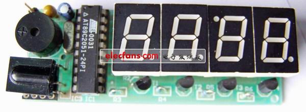
Front of the electronic clock
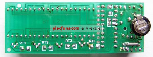
Back of the electronic clock
one. working principle
The DS1302 is a real-time clock chip from Dallas. Its main feature is serial data transmission, which provides programmable charging for power-down protection and can turn off charging. A common 32768 Hz crystal is used.
AT89C2051 as the main control chip, one is to judge and identify the received infrared remote control code, and perform the corresponding processing; the second is to periodically read the time in the clock chip DS1302 and show the hour and fat in the 4-bit LED The third is to compare the set alarm time with the real-time time. If the time is the same and the alarm is allowed, the buzzer will sound for one minute in a one-second period to remind the user. If you want to stop the beep, just press the corresponding button on the remote control to turn off the alarm. The alarm time is stored in the RAM of the DS1302 and does not require a separate EEPROM.
two. Hardware circuit
Figure 1 shows the schematic of the electronic clock. The IC2 is the DS1302. Electronic enthusiasts can request free samples from MAXIM. Y2 is a 32768 Hz quartz crystal, which can be used in ordinary electronic watches. IC3 is a three-legged plastic integrated infrared receiver. LED1-4 is a high-brightness digital
Digital Tube. The crystal oscillator Y1 used in the 89C2051 can be replaced by other 12M if it is not 10MHz. Just modify the delay parameters of YS1 and YS2 in the program to keep the delay length unchanged. Adjusting R2 can change the brightness of the digital tube. The P1 port is connected to the eight fields of the digital tube. The left two digits of the digital tube display the hour, the right two digits display the minute, and flash when the alarm time is displayed. The decimal points of the second and third digits flash as seconds. Note that the third digit tube is rotated 180° after installation according to Figure 1. In order to make “:†between the hour and the minute, the last one The decimal point is used as the alarm switch indicator, and the light indicates that the alarm is on. The buzzer B2 uses a small self-contained sound source.
To be specifically stated, the backup power supply B1 can be used with a battery or a super capacitor (100,000 uF or more). Although the DS1302 consumes a small amount of power after the main power supply is powered down, it is best to use a small rechargeable battery if it is necessary to ensure the clock is normal for a long time. You can use the 3.6V rechargeable battery on the old computer motherboard. If the power-off time is short (hours or days), you can replace it with a common electrolytic capacitor with less leakage. 100uF can guarantee 1 hour of normal walking time. The DS1302 must be initialized after the first power up. After initialization, you can adjust the time and alarm in the normal way.
three. software
The focus of the software section is on the operation of the DS1302 and the decoding of the infrared remote control. MCU decoding can refer to other articles, here mainly explain some of the settings:
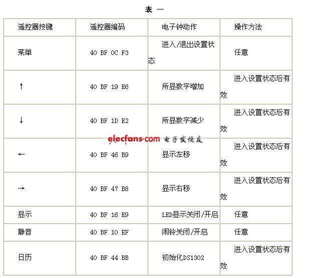
The remote control adopts the Changhong color TV K11F type remote controller, and the remote controller transmits according to the 16-bit address code, the 8-bit data code and the 8-bit data code. Table 1 lists the codes of the buttons and the actions corresponding to the electronic clock. If other remote controls are used, the code for the corresponding part of the program needs to be modified.
In the operation method, any means that the key is pressed after the first press, and is pressed again to exit the state.
Time setting: Press “Menu†to enter the setting state, LED only shows the hour of normal time, press “↑↓†to adjust the value, press “â†â€, “→†to move between alarm and normal time. Press the "Menu" button again at any time to exit the settings.
Alarm setting: The alarm time is performed in the time setting. Alarm Allow and Cancel Press the "Mute" button at any time.
Display switch: Press the “Display†button at any time to turn the display on and off.
Initialization: Press the “Calendar†button at any time after pressing the “Menu†button to enter the setting state. The time after initialization is 2002/12/1/12:00:00
LED wall washers are high
power LED lights that are used for decorative lighting and highlight, or wash
walls, of buildings, clubs, hotels, stages, parks, plazas, commercial building
facades, art galleries, etc., with different kind of colors.
The LED wall washer can even change their colors while projecting. The RGB LED
wall washer lights can project various colors and change the color by
programming the LED wall washer the way you want to. LED wall washers can be
used for clubs, stages, parks, plazas, commercial building, art gallery,
landscape, architectural decoration, etc.
LED Wall Washer Light
Indoor Wall Washer,Led Christmas Wall Washer,Led Light Wall Washer,Led Outdoor Wall Washer
ZHONGSHAN G-LIGHTS LIGHTING CO., LTD. , http://www.glightsled.com