Electricians rely on various tools to perform their tasks effectively, and among these, the clamp meter stands out as a frequently used device. Known also as a clamp-on ammeter or simply a clamp meter, this tool is essential for daily electrical maintenance. Primarily used to measure voltage, current, frequency, and other relevant parameters, it demands high precision, accuracy, and versatility. Whether dealing with AC or DC circuits, a clamp meter is indispensable for professionals.
First: Understanding the Principle of AC Clamp Meter Measurement
A clamp meter essentially combines a current transformer, a jaw-like structure, and a counter-reactive instrument equipped with a rectifying magnetoelectric system. In essence, it acts as a current transformer paired with an ammeter. The core of the clamp meter is designed to open, allowing a live conductor to be inserted into its core. When this happens, the conductor becomes the primary winding of the current transformer with one turn, while a secondary winding wrapped around the core connects to the measuring instrument. The measured current value can be directly read, making it highly convenient to measure current without interrupting the circuit.
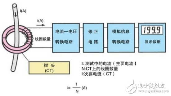
The working principle of an AC clamp meter typically follows the CT (current transformer) principle. By passing a conductor carrying the main current through the clamp, electromagnetic induction generates a secondary coil that produces a current proportional to the main current. This allows for precise measurements of AC current using a digital clamp meter. For a clearer understanding, refer to the accompanying flowchart:
Second: Important Precautions When Using a Clamp Meter
Before using a clamp meter, always read the instructions carefully to determine whether it measures AC or both AC and DC. Ensure the meter is properly zeroed before starting any measurements.
Select the appropriate range based on your initial estimation of the current being measured. Always start with a higher range and then adjust to a lower one if needed. Avoid exceeding the rated value indicated on the clamp meter, as doing so could result in grounding issues or even electric shock.
When measuring current, ensure that only one phase conductor is placed inside the clamp at a time. Position the conductor to be tested in the center of the clamp window to achieve accurate readings. Attempting to measure multiple conductors simultaneously within the same window will yield inaccurate results.
Estimate the approximate current before selecting the range. If unsure, begin with the highest range and gradually decrease it for a precise reading. Never use a small current range to measure large currents, as this may damage the meter.
Ensure the jaws are closed tightly during measurement. If you hear noise upon closing, reopen and reclose them. If the noise persists, inspect the magnetic circuit joints for dirt or debris and clean them as necessary.
Due to the inherent limitations of clamp meters, especially when measuring small currents, a workaround exists. Wrap the circuit wire several times around the clamp meter's jaws. The reading displayed is not the actual current but rather the result of dividing the reading by the number of wire turns. The formula is: reading = indication value × range / full scale × number of turns.
After completing the measurement, set the range selector back to the lowest position. Always avoid operating the clamp meter under live conditions to prevent electric shock.

Third: How to Use a Clamp Meter to Measure Resistance
Measuring resistance with a clamp meter requires a slightly different approach than measuring current. Follow these steps:
- Insert the red test lead into the “VΩHz†jack and the black test lead into the “COM†jack.
- Set the function range switch to the resistance mode and connect the test leads to the resistor being tested.
- Read the measurement results from the display.

While clamp meters are primarily designed for current measurement, they can also measure resistance with the right setup. However, for more complex electrical diagnostics, specialized tools may be required. Always follow safety guidelines and consult the user manual for specific instructions tailored to your device model.
Transmission Line Steel Tubular Pole
We have got 220kV Transmission Line poles Quality Certificate from Power Industry Steel Tower Qualified Inspection & Test Center from 2001 year. Our steel poles are made from quality sheet through bending, forming, automatic welding and hot galvanization. We can reach one-run machining length of 14m and can bend sheet of thickness up to 45mm. We adopt advanced welding procedures, automatically weld main joints and reach rank-II welding quality.
We have supplied 2400ton 132kV and 220kV transmission line steel pole to WAPDA. Pakistan on 2008 and have supplied 1200ton 138kV transmission line steel pole to Davao light, Philippines on 2009.
Transmission Line Steel Tubular Pole, Tubular Steel Pole, Steel Tubular Pole, Utility Pole
JIANGSU XINJINLEI STEEL INDUSTRY CO.,LTD , https://www.steel-pole.com