In recent years, traditional lighting systems have been largely controlled through wires and mechanical means, which limits their flexibility and efficiency. Recognizing these limitations, this article introduces an innovative approach leveraging Internet of Things (IoT) technology. By embedding an intelligent control module into LED lighting terminals, this system integrates embedded technology, wireless sensor networks, and more to enable intelligent, digital, and wireless lighting control. Additionally, the system features monitoring capabilities for parameters like ambient temperature, humidity, and illuminance.
**Overview**
With the growing popularity of LED lighting and advancements in mobile internet technology, people are increasingly seeking ways to integrate their home appliances, including lighting fixtures and security systems, into unified control platforms for smarter management. As IoT continues to evolve, smart LED lighting has become a key component of this ecosystem.
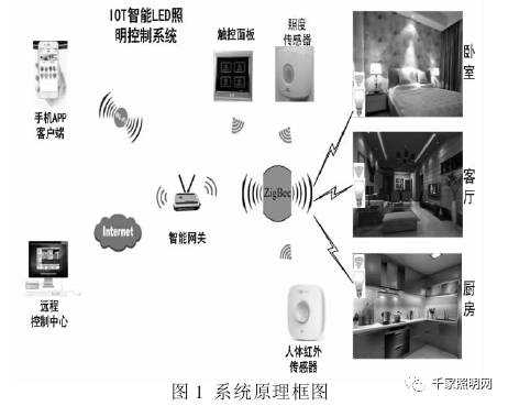
This article presents an intelligent LED lighting control system designed to promote "Green Smart Lighting." Using IoT and embedded technologies, the system allows users to remotely control various lighting modes of LED lamps via wireless connectivity. It monitors the ambient illumination and operational status of LED lamps in real-time within their working range. Furthermore, sensor technology enables adaptive adjustments to illumination levels and color conversions, creating a comfortable, energy-efficient, and secure lighting environment. Figure 1 illustrates this concept:
**System Hardware Design**
The hardware design of the system comprises an LED lighting control terminal and a touch panel, which together facilitate intelligent lighting management of LED lamps. The primary components include a control module, communication module, power module, and others.
**(1) Main Control Unit Design**
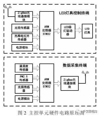
The main control unit of the LED intelligent lighting system consists of two main parts: the LED lighting control terminal and the data acquisition terminal. The LED lamp control terminal features an ARM processor (STM32) as the core, along with a power supply circuit, peripheral circuitry, and an illumination sensor. The data acquisition terminal incorporates temperature and humidity sensors, illuminance sensors, and PM2.5 sensors. The hardware circuit schematic is shown in Figure 2 below:
**(2) Touch Panel Hardware Design**
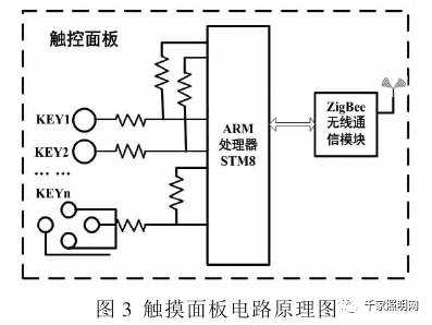
The touch panel’s hardware design utilizes the new-generation ARM processor STM8S. The STM8S series processor comes equipped with a touch software library, enabling capacitive touch sensing through the charge transfer characteristics of capacitors. This setup primarily handles the switch buttons for LED lighting fixtures and scroll bars for brightness adjustment. The circuit schematic is depicted in Figure 3:
**(3) ZigBee Wireless Communication Module Design**
To implement centralized management and environmental monitoring functionalities, this system employs a ZigBee wireless module based on IoT technology. The system’s ZigBee wireless communication module uses the CC2530 module, which is a true system-on-chip (SoC) CMOS solution from Texas Instruments. The CC2530 offers excellent performance, low cost, and minimal power consumption, combining a high-performance 2.4GHz DSSS (Direct Sequence Spread Spectrum) RF transceiver core with an industrial-grade 8051 controller.
**(4) Power Module Design**
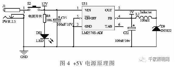
Considering the application in a household setting where the primary power source is typically 220V AC, the power module is designed using multiple discrete components to generate various voltage outputs. A switching power supply converts the 220V AC into a 12V DC supply. The +12V to +5V conversion uses the LM2576 series regulator, capable of handling up to 3A loads with excellent linearity and load regulation. The schematic for the +5V power supply is shown in Figure 4:
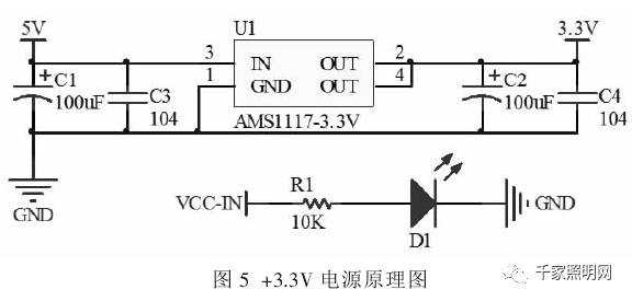
For the +5V to +3.3V conversion, the AMS1117 voltage regulator is employed. The AMS1117 can deliver up to 1A of output current with a minimum input voltage of 1V. Once regulated to +3.3V from +5V, it powers the CPU and other chips. The schematic for the +3.3V power supply is shown in Figure 5:
**System Software Design**
The software design focuses on collecting and transmitting data related to LED intelligent lighting control and environmental conditions. Through the ZigBee wireless communication network, the system achieves centralized management and data collection for LED lamps.
**Conclusion**
By studying relevant theoretical knowledge, this paper enhances LED lamp brightness and color control based on LED characteristics. Adding brightness and human detection sensors, the system achieves an intelligent, digital, and networked LED lighting system. The design and structure are reasonable, maximizing the potential of intelligent lighting technology to meet LED lighting applications. The system demonstrates excellent expandability, energy savings, and practical application value, offering significant market prospects.
Despite the challenges in implementing such advanced systems, the integration of IoT and embedded technologies holds immense promise for revolutionizing how we interact with lighting and manage our environments.
Automotive Wire Harness,Power Offer Cable Harness,Data Signal Cable Harness,Auto Signal Cable Assemblies
Dongguan City Yuanyue Electronics Co.Ltd , https://www.yyeconn.com