There is an interesting connection between complex mixers, zero-IF architectures, and advanced algorithm development. The purpose of this paper is to clarify the basic concepts of each of the three, namely the working principle and the value they bring to the system design, and explain the interdependence between them.
RF engineering is often seen as a black magic in the electronics field. It may be a peculiar combination of mathematics and mechanics, sometimes just a trial and error. It has left many excellent engineers unsolvable, and some engineers only know the results and know nothing about the details. Many existing literatures often do not establish basic concepts, but jump directly to theoretical and mathematical interpretations.
Complex RF mixer revealsFigure 1 is a schematic diagram of a complex mixer configured with an upconverter (transmitter). The two parallel paths each have an independent mixer, and a common local oscillator feeds the signals to the path, and the local oscillator is 90° out of phase with one of the mixers. The two independent outputs are then summed in the summing amplifier to produce the desired RF output.
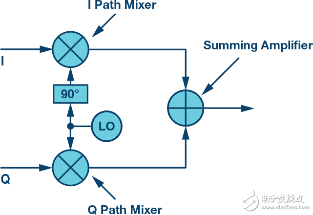
Figure 1. Basic architecture of a complex transmitter
This configuration has some simple but very useful applications. Assume that only one tone is fed on the I input without driving the Q input, as shown in Figure 2. Assuming that the signal tones on the I input are x MHz, the mixer in the I path produces an output of the LO frequency ±x. Since no signal is applied to the Q input, the spectrum produced by the mixer in this path is empty, and the output of the I mixer becomes the RF output directly.

Figure 2. I path analysis
Alternatively, assume that only one tone of frequency x is applied to the Q input. The Q mixer in turn produces an output with a signal tone of the LO frequency ±x. Since no signal is applied to the I input, its mixer output is muted and the output of the Q mixer becomes the RF output directly.
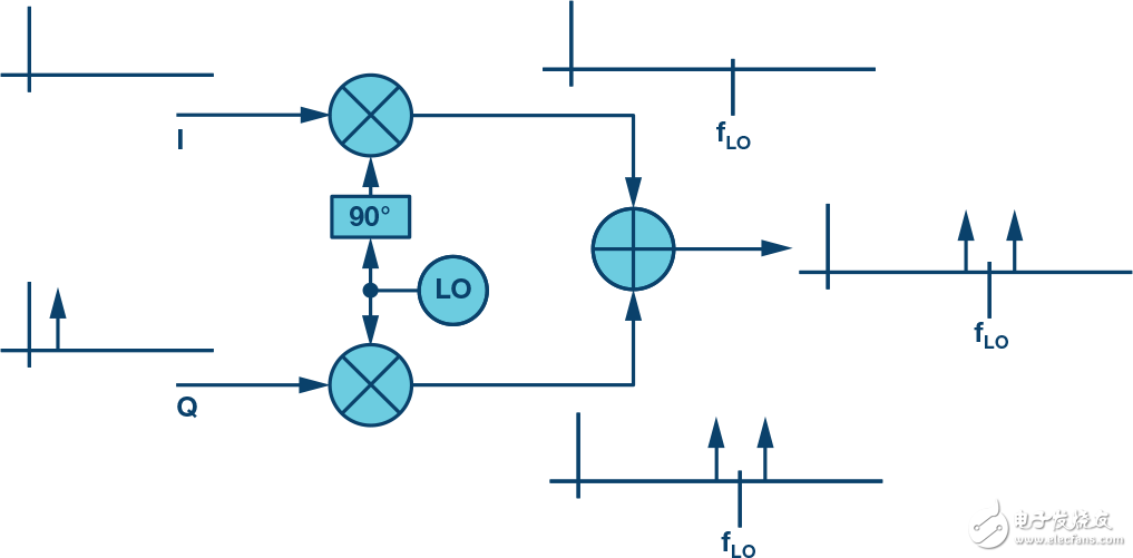
Figure 3. Q path analysis
At first glance, the output of Figures 2 and 3 seems to be identical. But in fact, there is a key difference between the two, that is, the phase. Assume that the same tone is applied to both the I and Q inputs simultaneously, and there is a 90° phase shift between the input channels, as shown in Figure 4.

Figure 4. Path analysis of simultaneous I and Q signals
Looking closely at the mixer output, we observe that the LO frequency plus the input frequency signal is in phase, but the LO frequency minus the input frequency signal is out of phase. This causes the signal tones on the upper side of the LO to be added, and the signal tones on the lower side to cancel. Without any filtering, we eliminate one of the tones (or sidebands) and produce an output that is completely on one side of the LO frequency.
In the example shown in Figure 4, the I signal is 90° ahead of the Q signal. If the configuration is changed such that the Q signal is 90° ahead of the I signal, then similar additions and cancellations can be expected, but in this case all signals will appear on the lower side of the LO.
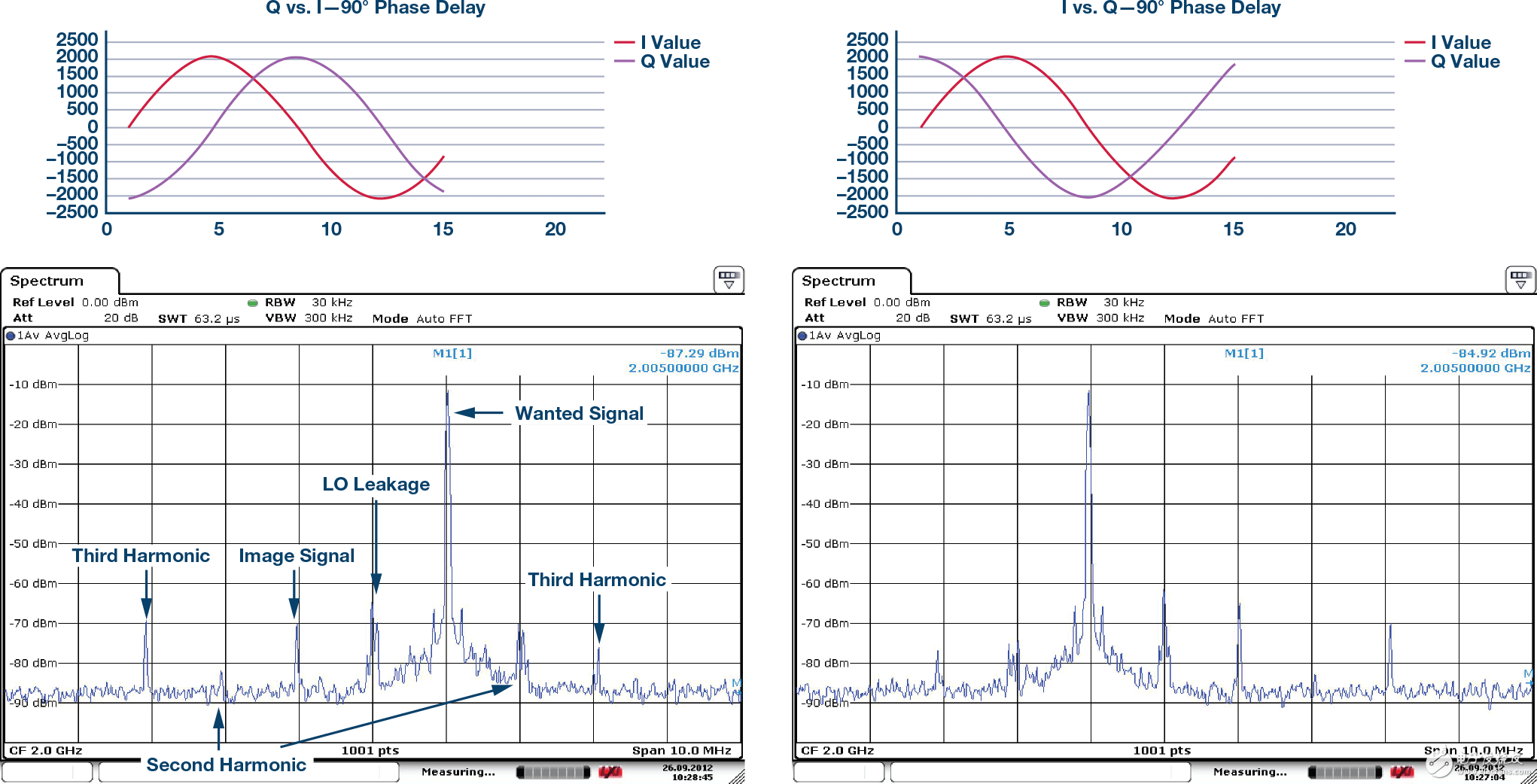
Figure 5. Signal tone position depends on the phase relationship between I and Q
Figure 5 above shows the laboratory measurements of a complex transmitter. Shown on the left is a test case where I is 90° ahead of Q, which causes the output signal to be on the upper side of the LO. The opposite relationship is shown on the right side of Figure 5, that is, Q is 90° ahead of I, and the resulting output tone is located on the lower side of the LO.
In theory, it should be possible to let all the energy fall on only one side of the LO. However, as shown by the laboratory measurements in Figure 5, complete cancellation is not possible in practice, and some energy will remain on the other side of the LO. This is called mirroring. It should also be noted that the energy of the LO frequency is also present, known as LO leakage or LOL. Other energy can be seen in the results - these are the harmonics of the desired signal and are not discussed in this article.
In order to completely eliminate the mirroring, the amplitudes of the I and Q mixer outputs must be exactly the same, and the phase between them on the LO mirror side is exactly 180° out of phase. If the above phase and amplitude requirements are not met, then the addition/destruction process shown in Figure 4 will be less than ideal, and the energy of the image frequency will still be present.
influencesLO±products are produced using a conventional single mixer architecture. One of the sidebands needs to be eliminated before transmission, usually by adding a bandpass filter. The roll-off frequency of the filter must be appropriate so that it eliminates unwanted image signals without affecting the desired signal.
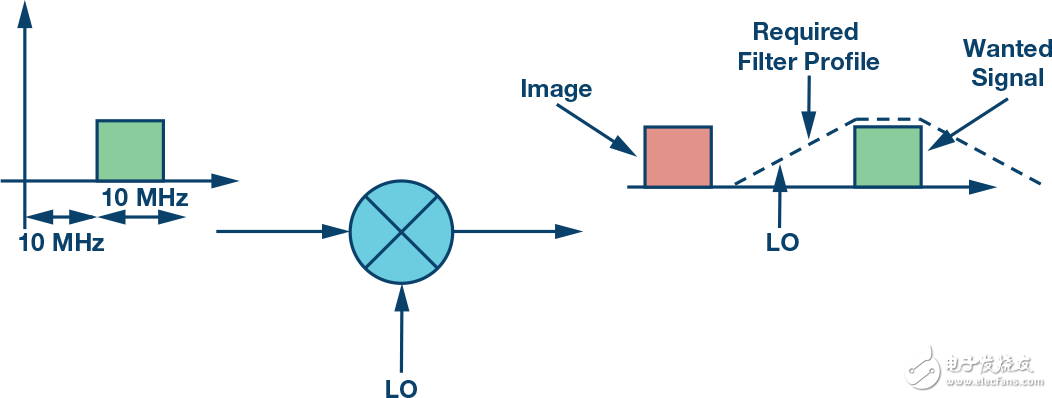
Figure 6. Single Mixer Mirror Filter Requirements
The spacing between the image and the desired signal directly affects the filter requirements. If the interval is large, a simple, low-cost filter with a gentle roll-off can be used. If the spacing is narrow, the design must implement a filter with a steep response, usually with a multipole or SAW filter. It can therefore be said that the appropriate spacing must be maintained between the image and the desired signal so that the image can be filtered out without affecting the desired signal; this spacing is inversely proportional to the complexity and cost of the filter. In addition, if the LO frequency is variable, the filter must be tunable, which further increases the complexity of the filter.
The spacing between the image and the desired signal is determined by the signal applied to the mixer. The example in Figure 6 shows a 10 MHz bandwidth signal 10 MHz from DC. The corresponding mixer output places the image at 20 MHz from the desired signal. In this configuration, to achieve a desired signal spectrum of 10 MHz at the output, a 20 MHz baseband signal path must be connected to the mixer. The baseband bandwidth of 10 MHz is unused and the data interface rate of the mixer circuit is higher than necessary.
Returning to the complex mixer shown in Figure 5, we know that its architecture eliminates mirroring without external filtering. Moreover, efficiency can be optimized in a zero-IF architecture such that the signal path processing bandwidth is equal to the desired signal bandwidth. The conceptual diagram shown in Figure 7 illustrates the implementation principle. As described above, if I is 90° ahead of Q, only the upper side of the LO will have an output. If Q is 90° ahead of I, there will be only an output on the lower side of the LO. Thus, if two separate baseband signals are generated, one designed to produce only the upper sideband output and the other designed to produce only the lower sideband and the other designed to produce only the lower sideband output, then it can be added and applied to the baseband. Complex transmitter. The result will be that the outputs with different signals appear on the upper and lower sides of the LO. In practical applications, the combined baseband signals are generated digitally. The summing node shown in Figure 7 is only for the purpose of illustrating this concept.
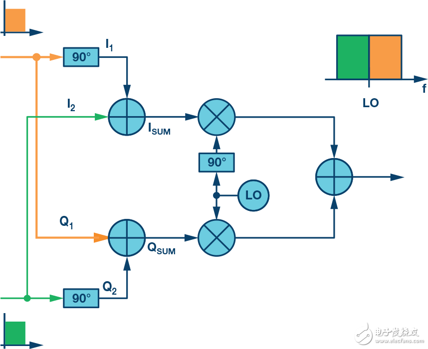
Figure 7. Zero IF Complex Mixer Architecture
Germany Cable Reel,Cable Reel,Automatic Cable Reel,Cable Spool Reel
CIXI KYFEN ELECTRONICS CO.,LTD, , https://www.kyfengroup.com