The autonomous mobile robot system refers to an autonomous path planning based on command tasks and environmental information, and continuously collects local environmental information during the task execution process to make decisions, thereby realizing safe driving and accurately reaching the target site. This paper introduces the design scheme of a wheeled mobile robot with LPC2119 as the control core. The robot system uses ultrasonic sensors, photosensitive sensors and collision sensors to collect external environmental information, and uses PTR2000 to realize communication between mobile robots and computers, thereby realizing feedback of on-site information and transmission of computer control commands.
The LPC2119 is an ARM7TDMI-S microprocessor from Philips that supports real-time emulation and tracking, embedding 128KB of high-speed flash memory. It uses 3-stage pipeline technology, which takes instructions, decodes and executes simultaneously, and can process instructions in parallel to improve CPU speed. Due to its very small size and extremely low power consumption, it is ideal for miniaturized applications. Up to 64KB of SRAM on-chip, with a large buffer size and powerful processing power. The LPC2119 integrates two CAN controllers, two 32-bit timer counters and four ADC unit circuits.
1 hardware structure
The controller LPC2119 is mainly used to generate 2 PWM signals and process sensor information to realize intelligent control of the car. The system uses IR2110 as the H-bridge circuit driver chip, uses four STP60NE06 lap H-bridge circuit to drive DC motor, and uses photoelectric encoder to detect motor speed; 16-channel ultrasonic sensor system is used as system collision avoidance and simple ranging; The photosensitive sensor realizes the perception and search of the light source by the robot; the collision sensor is used to sense the collision, so that the robot can make the emergency processing; the wireless communication chip PTR2000 is used to realize the wireless communication between the robot and the computer.
1.1 PWM control of the motor
The IR2110 is a two-channel, high-voltage, high-speed power device gate-driven monolithic integrated driver from IR (InternaTIonal RecTIfier). It integrates most of the functions required to drive high-side and low-side MOSFETs or IGBTs in a high-performance package, with few discrete components providing extremely fast switching speeds and extremely low power consumption. The utility model is characterized in that: the input logic signal is converted into the same phase low-impedance output driving signal, and the two-channel output on the same bridge arm can be driven, the driving capability is strong, the response speed is fast; the working voltage is high, up to 600V; the internal undervoltage is set Blockade; low cost, easy to debug; small circuit chip, DIP14 package. The high-side driver uses external bootstrap capacitors to power up. Compared with other IC driver circuits, the design greatly reduces the number of drive transformers and capacitors, reduces product cost, reduces the size, and improves system reliability. This bootstrap integrated circuit for driving power MOSFETs and IGBTs has been widely used in power drive fields such as power conversion and motor speed regulation.
The PWM function of the LPC2119 microcontroller is built on a standard timer. It has a 32-bit timing controller and prescaler controller, and 7 matching controllers. It can realize 6 single-sided PWM or 3 bilateral PWM outputs. It can also be used. These two types of mixed outputs. This system uses the port PWM0 and PWM1 to output two PWM signals to control the two drive motors of the mobile robot. The PWM signal is applied to the HIN and LIN pins of the IR2110 through the optocoupler to form two signals with 180° phase difference, which realizes the control of the two MOSFET switches on the same bridge arm. The principle is shown in Figure 1.

When HIN is high level, Q1 and Q4 are turned on, and the forward working voltage is applied to the DC motor. When HIN is low level, the LIN terminal inputs a high level, Q2 and Q3 are turned on, and the DC motor is reversed. Operating Voltage. Therefore, the operating voltage on the armature is a bipolar rectangular pulse waveform. Due to the effect of mechanical inertia, the average value of the rectangular pulse voltage determines the steering and rotational speed of the motor.
1.2 Ultrasonic sensor system
To reduce the burden on the controller LPC2119, the ultrasonic sensor system is controlled by Atmel's AT89C1051 microcontroller. The 1051 microcontroller is a high-performance microcontroller with a 1KB programmable E2PROM that is instruction and pin compatible with the industry standard MCS-51. It provides a highly flexible and efficient solution for many embedded control applications. The AT89C1051 has the following features: 1KB E2PROM, 128B RAM, 15 I/O lines, 2 16-bit timer/counters, 5 second-level vector interrupt structures, 1 full-bidirectional serial port and precision analog comparison The device and the on-chip oscillator have a voltage operating range of 4.25~5.5V and a working frequency of 24MHz. They also have a secondary program memory lock, power-down and clock circuit of the encryption array. In addition, the AT89C1051 also supports two power-saving modes of software settings. When idle, the CPU stops and the RAM, timer/counter, serial port, and interrupt system continue to operate. When power is lost, the contents of the RAM are saved, but the oscillator is stopped to disable other functions of the chip until the next hardware reset.
The 1051 control sends an ultrasonic wave every 60 ms, detects the echo time, and completes the calculation of the distance. In this way, the 16-channel ultrasonic cycle detection is about 1 s at a time, and the ultrasonic wave speed is about 344 m/s at normal temperature, the distance of the obstacle can be calculated, and finally the ultrasonic sensor number and distance information are transmitted to the LPC 2119.
The ultrasonic transmitting and receiving subsystem is shown in Figure 2. 1051 uses the P1.0 pin to send a 40kHz pulse signal. This signal is used as the enable signal of the 4-16 decoder 74HC154. Pins P1.1~P1.4 are used as the decoding signals, corresponding to the numbers 0~15. Ultrasonic sensor. This signal is amplified by 9013 and then the transducer is driven to generate a 40 kHz ultrasonic signal.
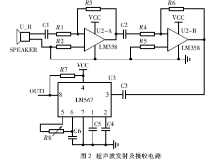
LM567 is a phase-locked loop circuit. The external resistors and capacitors of pins 5 and 6 determine the center frequency f2 of the internal voltage-controlled oscillator, f2≈1/1.1RC. Its 1 and 2 feet are respectively grounded through a capacitor to form an output filter network and a loop single-stage low-pass filter network. The capacitance of the 2 pin determines the capture bandwidth of the phase-locked loop: the larger the capacitance, the narrower the loop bandwidth. The LM567 operates from 4.75 to 9V, operates from DC to 500kHz, and has a quiescent operating current of approximately 8mA.
The basic function of the ultrasonic subsystem is: when the receiver receives the ultrasonic echo, it generates an AC small signal. After the LM358 is composed of a 2-stage amplifying circuit, the amplitude is above 25mV. When the LM567's 3-pin input signal with amplitude ≥25mV and frequency is 40kHz, the 8 pin changes from high level to low level. This low level signal is connected to the INT0 pin of 1051 to generate an interrupt signal. The 1051 starts the timer when the ultrasonic wave is transmitted, and turns off the timer when the INT0 is interrupted, thereby obtaining the propagation time of the ultrasonic wave and calculating the obstacle distance.
The system has been used to measure a plane object with a measurement range of 30~400cm. The maximum error is 0.5cm and the repeatability is good. If the driving current of the ultrasonic wave is increased, the amplifying circuit of the receiving portion is further increased by one step, so that the detecting distance can be increased to 600 cm.
1.3 wireless communication subsystem
This system uses the micro-miniature, low-power, 19.2kbps wireless transceiver MODEM chip PTR2000 to realize wireless communication between the robot and the computer. The chip's operating frequency is 433MHz, the internationally-used digital transmission band, which uses FSK modulation and can be connected to the RS232 interface of the computer. The communication protocol adopted by the system is as follows:
[Start character] [Data 1] [Data 2] ... [Checksum] [End character]
Connect the DO and DIN pins of the PTR2000 to the TXD0 (13 pins) and RXD0 (14 pins) of the LPC2119 as the channels for serial communication. CS is the frequency selection signal of the PTR2000 module; PWR is the module energy-saving pin, and the normal operation is high level. TXEN is the module transmit and receive control, controlled by the I/O port of the LPC2119. The PTR2000 is an integrated transceiver chip that operates from a 3.3V supply and can be seamlessly connected to the LPC2119. When the PTR2000 is connected to a PC as a transmitter, it needs to be converted to an RS-232 level by a level shifter (here MAX3232). The PLC2119 can set the wireless transceiver module PTR2000 to the transmitting or receiving state by setting or clearing the output port; the control of the serial port of the computer can be realized by the RTSEnable attribute of the MSComm control of the VB.
1.4 Photosensitive sensor subsystem
The photosensor used by the robot is a cadmium sulfide photocell (CDS). The resistance value of the cadmium sulfide phototube varies with the amount of surface light that is irradiated. The stronger the light, the smaller the resistance value. Cadmium sulfide phototubes are also commonly referred to as photoresistors. The resistance value of CDS can make a large change to less light, and it is a kind of photosensitive sensor which is more commonly used in robot systems. Eight identical photosensors are evenly distributed on the robot body to sense the change in light intensity around the robot. By collecting the output voltage of each sensor, the path of the robot is determined by a software algorithm, so that the robot always walks in a direction of stronger light to realize the search for the light source.
A precision resistor is placed in series with the CDS device. This resistor acts as a voltage divider to convert the resistance of the CDS device to the appropriate voltage value for the analog-to-digital converter (ADC). The divided output of the CDS device is output to the ADC, and the voltage value is then converted to a digital value. When more light is shining on the CDS device, both its resistance and the voltage output on the ADC are reduced. Generally, the resistance of this precision resistor is equal to the maximum resistance of the CDS device.
2 software programming
The software design of the system is different due to different tasks. The task of the mobile robot system is to find the light source autonomously in a closed environment of known size and dark light.
After the system software starts, it performs self-test and initialization of the system, and then performs path planning. First, traverse the entire environment horizontally. If the light source is found, the robot stops moving and waits for the command. If the light source is not found, the entire environment is traversed vertically. If the light source is found, the robot stops moving; if it is still not found, an error message is displayed. When the ultrasonic subsystem finds an obstacle in front or the robot collides with the obstacle, an external interruption will be generated to terminate the operation of the program, and the controller LPC2119 will receive the obstacle distance or collision information, and thereby re-plan the path. Autonomous operation of the robot.
This design is an in-vehicle embedded system based on ARM7 microprocessor, which not only meets the requirements of mobile robot control system, but also provides good technical support for the transformation application of robot. On this basis, various advanced control algorithms can be added to realize the intelligence of mobile robots.
Transformer For Renewable Energy
Transformer For Renewable Energy, Solar Transformer,Wind Mill Transformer, Energy Station
Hangzhou Qiantang River Electric Group Co., Ltd.(QRE) , https://www.qretransformer.com