O Introduction
The new type of rapid electromagnetic casting and rolling technology for aluminum alloy strips uses an electromagnetic induction device to generate an alternating composite magnetic field to perform comprehensive control of electromagnetic stirring and electromagnetic disturbance on the aluminum melt in the casting and rolling zone to change the solidification and crystallization conditions of aluminum and aluminum alloys. In order to achieve the purpose of refining grains and improving the structure and properties of cast-rolled slabs.
1 Fast electromagnetic casting and rolling system for aluminum alloy strip
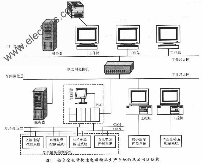
The aluminum alloy strip rapid electromagnetic casting and rolling production system is a complex large system. It is mainly composed of three parts: casting and rolling special power supply control system, furnace temperature control system and rolling mill drive control system. There are a lot of enterprise management and decision-making information and real-time on-site information in this system that need to be coordinated and processed. In order to meet the needs of integration and comprehensive automation of the aluminum production process, this design uses a networked structure based on industrial Ethernet and fieldbus technology. Figure 1 shows a schematic diagram of the three-layer network structure of the aluminum alloy sheet and strip rapid electromagnetic casting and rolling production system. It can be seen from the figure that it integrates with industrial Ethernet and field bus technology, thereby effectively solving the basic automation control network and process and The problem of seamless integration between management and control systems also provides good necessary conditions for ERP (Enterprise Resource Planning) management. The following mainly designs the communication system based on CANopen protocol field device layer.
2 Introduction to CANopen
CAN (Controller Area Network) is the abbreviation of Controller Area Network. It is a serial data communication bus developed by the German Bosch company in 1986 to solve the data exchange problem between many measurement and control components in modern automobiles. The bus has now been included in the ISO international standard (called ISO 11898). CAN fieldbus network is a serial communication network that can effectively support distributed control and real-time control. It has high real-time, reliability, anti-interference ability and error detection ability, which is very suitable for aluminum alloy strip fast electromagnetic Application of distributed network monitoring system in casting and rolling production process.
In the OSI reference model, the network system structure is divided into 7 layers. CAN only defines the first layer (physical layer) and the second layer (data link layer), these two layers are completely implemented by hardware. Since there is no application layer defined, it is incomplete, and a high-level protocol is needed to define the use of the 11 / 29-bit identifier and 8-byte data of the CAN message. CANopen is a standardized application layer protocol based on the physical layer and data link layer of the CAN protocol. It includes application layer specifications, communication protocols, and device protocols. CANopen is a public, open, and universal protocol that can provide a standard and unified communication mode and device function description in the CAN network, and can perform network management functions. In addition, because it adopts object-oriented thinking design, it has good module characteristics and high adaptability, and is concise and transparent, easy to develop.
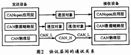
In the CANopen application layer, communication objects (COB) are exchanged between devices, and they are mapped to CAN frames with identifiers (ID) and transmitted on the data link layer. At the physical layer, the signal appears in the form of a "differential" voltage between the two lines of the sun, and "Dominant" and "Recessive" two complementary logical values ​​are used to represent "0" and "1". Figure 2 shows the communication relationship between the protocol layers.
The CANopen protocol classifies the data transmitted on the bus, that is, each transmitted data is an object of a specific class, thereby implementing object-oriented programming. There are four types of communication objects defined in the data transmission based on the CANopen protocol: one is the process data object (PDO) used to transmit real-time data; the second is the service data object (SDO) used to access the device configuration parameters in the object dictionary; three It is a special function object, which includes synchronization (SYNC) object and emergency (Emergency) object; the last is the time stamp (TIme Stamp) object.
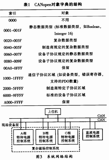
Each type of communication object in CANopen has its standardized format, so it can achieve the unity of the application layer structure. In order to realize the standardization and convenient management of various objects, the concept of object dictionary (ObjectDicTIonary, OD) is defined in the CAN-open protocol. Each device has a unique object dictionary, which describes all data types used by the device, including all parameters that describe this and the behavior of the network. The object dictionary is a medium specifically used for data exchange between CAN bus communication interfaces, and is the core of the entire CANopen protocol. The structure of the CANopen object dictionary is listed in Table 1.
3 System hardware design
3.1 Network system structure
The communication system based on CANopen is composed of the power control system (including the three-phase special power control system and the DC auxiliary power control system) of the host computer and the field device layer. The upper computer communicates with the lower computer through the CAN field bus to realize real-time monitoring and control system functions. Each subsystem also communicates via CAN bus connection. The communication network topology adopts a bus structure. The system network structure is shown in Figure 3.
3.2 Communication system design of lower computer
The design based on "MCU + CPLD" is an important realization form of current digital circuit research and development. This control system combines MCU and CPLD for special power supply control of aluminum electromagnetic field rapid continuous casting and rolling, and uses it as the control core of the system.
MCU adopts MSP430F1611 of American TI company, this device is one of 16 ultra-low power consumption MSP430 series microcontrollers. MSP430 series single-chip microcomputer (or called microcontroller) is a powerful single-chip microcomputer with ultra-low power consumption features. It has multiple sub-series, of which MSP430F1x sub-series is a MCU with FLASH developed by TI in 2000 and its memory Capacity and on-chip peripheral modules vary with specific models, and users can choose according to their needs. The hardware block diagram of its control system is shown in Figure 4.
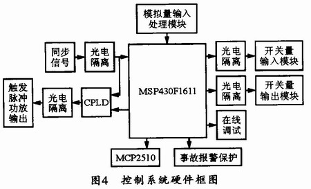
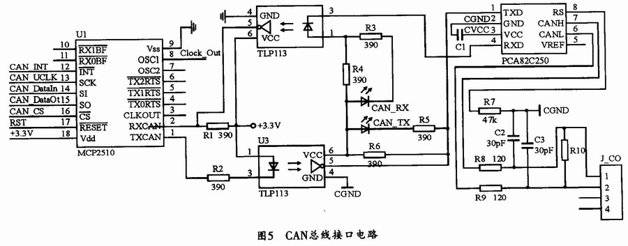
CANopen communication protocol can be realized by CAN communication controller. Since there is no integrated CAN controller module inside the MSP430F16ll, it needs to be expanded on the periphery. This design selects the MCP2510 of American Microchip Company as the CAN bus communication controller of the system. Figure 5 shows the CAN bus communication interface circuit. MCP2510 is an independent CAN controller with SPI interface, it fully supports the CAN bus V2.0A / B technical specification, the communication rate is lMbps, the chip contains three transmit buffers and two receive buffers, which can reduce the management burden of the MCU . The PCA82C250 used by the CAN bus transceiver is the interface between the CAN controller and the physical bus, and can provide differential transmission and reception functions to the bus. Two high-speed photoelectric isolation devices TLPll3 are used to improve the anti-interference ability of the communication circuit, prevent interference signals on the bus from entering the controller and MCU, and also complete the conversion of 3.3V and 5V levels between MCP2510 and 82C250.
The USART interface of MSP430F16ll can support two different serial protocols, namely universal asynchronous protocol (UART protocol) and synchronous protocol (SPI protocol). Use the control bit SYNC in the control register UCTL to select the desired mode. When SYNC is 0, select the asynchronous mode UART; when SYNC = 1, select the synchronous mode SPI. MCP2510 can interface with the SPI of the USARTl communication module.
3.3 Host computer design
The upper computer should be able to complete the functions of monitoring and parameter setting of the lower computer. The quality of his hardware selection and structural design directly affect the work efficiency of the system site. This system selects the method of combining PLC and touch screen to design and monitor the host computer. Among them, PLC is the center of the upper computer. Using PLC to realize the monitoring of the upper computer is more in line with the requirements of on-site operation than using industrial computers to monitor the upper computer. Can easily achieve logic control. The monitoring adopts touch screen technology, which is also simpler and more convenient than keyboard and mouse operation, and more in line with on-site operation habits, which can greatly improve the efficiency of on-site operation.
This design uses the Twido series PLC of Schneider. Twido PLC has a variety of different communication methods and interfaces, including industrial Ethernet, CANopen, MODBUS, AS-I. Generally, it has at least one standard RS-485 / 422 serial communication interface, and the calculation speed is fast, the PLC cycle is short, and the expansion performance is good. Twido PLC not only has many switch I / O expansion modules, but also has many special function modules for users to choose, so it can greatly improve the control performance of PLC. The processor in the system can choose TWDLAE40DRF, which is an integrated controller with 24 points input, 14 points relay output and 2 points source transistor output, with an RS-485 port and an RJ-45 Ethernet The network port can be directly connected to the industrial Ethernet to communicate with the upper network. The controller itself does not have CAN communication function, but can realize CAN field bus communication based on CANopen protocol through external CANopen master station module TWDNC01M.
The TWDNC01M CANopen master module can be installed on the expansion bus of the PLC. It supports 16 slave devices, but does not support the extended addressing of CAN slave devices. Its transmission speed depends on the bus length and cable length. The bus connector for connecting to the CAN field bus is located in the middle and lower part of the TWDNC01M CANopen master module and contains the pins CAN_L (CAN_L bus line) and CAN_H (CAN_H bus line). The PLC has differential receiving and sending capabilities through these two The bus terminal is connected to the CAN bus.
To cooperate with the work of PLC. The monitoring platform should select a man-machine interface (touch screen) that is easy to operate. This system selects eView's MT500 series touch screen MT510, and its supporting software is EasyBuilder. EasyBuilder is a configuration software, mainly used to configure various components. The software is specifically for PLC applications, its function is very powerful, very easy to use, can fully meet the huge workload and functional requirements of modern industry.
The eView MTS00 touch screen defines two communication interfaces, RS-232 and RS-485. This design uses the RS-485 interface for definition. The Twido series PLC is connected to the e-View MT500 touch screen through the communication port on the CPU unit, and they use Modbus protocol for communication.
4 System software design
4.1 CANopen identifier
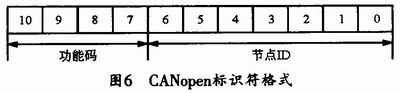
The communication object identifier (COB-ID) can uniquely determine each communication object and its priority in the CAN network. The size of the priority of the communication object can be determined by the size of the identifier value, and the smaller the value of the identifier, the higher the priority. The identifier of the CANopen information frame is divided into two parts, one part is a 4-bit function code and the other part is a 7-bit node ID. The function code represents the priority of the data frame, and the node ID is used to distinguish different nodes. The format of the identifier is shown in FIG. 6.
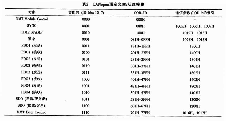
The assignment of identifiers can be achieved by a predefined master / slave connection set. It can also be dynamically allocated by the CALDBT service. Since the allocation of identifiers in most communication systems can be achieved by a predefined master / slave connection set, the system also uses a predefined master / slave connection set to implement the allocation of CANopen identifiers. Table 2 lists CANopen scheduled master / slave connection set.
4.2 Software design of CANopen protocol stack
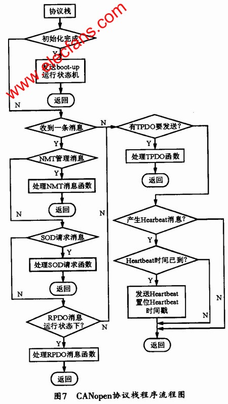
The software content of the CANopen protocol stack from the node is very rich, including node communication initialization and hardware device initialization, CAN message basic communication, definition and access object dictionary, NMT slave node function, PDO communication, SDO communication and node protection and other functions . The program flow chart is shown in Figure 7.
4.3 Configuration of CANopen master module
After the hardware connection is connected, the CANopen fieldbus master module can be configured through the CANopen configuration tool of Twidosoft V3.0 or higher. The configuration of the master and slave configuration and communication parameters of the CANopen network can only be performed in offline mode, and except for a few parameters that can be adjusted (such as% IWC and% QWC PDO addressing parameters), other parameters are not allowed
Online mode configuration.
5 Conclusion
The experimental results show that the CANopen communication system designed in this paper can achieve good results, and can realize the functions of displaying, setting, historical records and report printing of the casting power system parameters of the field device layer. Complete the centralized management and monitoring of frequency conversion power supply A, B, C three-phase and auxiliary power supply.
About Silicone Swim Cap :
Swim Cap is necessary quaipment for swimming,you need to wear it to protect your ears,hair,prevent water from entering your ears,and protect your hair from water damage.Our swim cap is made of silicone,you can call it Childrens Swimming Hats and Silicone Swim Caps .It's Waterproof Swimming Hat.And it won't take up space.It can not break easily.If you are looking for swim cap,how about our new products like Long Hair Silicone Swim Cap,Fun Silicone Swim Caps, Custom Swim Caps ?Hope can receive your message and start our story!
Silicone swim cap introduction:
1.Product name: Childrens Swimming Hats,Silicone Swim Caps,waterproof swimming hat,Long Hair Silicone Swim Cap,fun silicone swim caps,custom swim caps
2.Place of origin:Guangdong China
3.Color:any pantone color
4.Logo:Printing
5.MOQ:500pcs.
6.Package:1 pcs/opp,customized design is available.
7.Design:Customized/stock
8.Certification:FDA,LFGB,SGS,ROHS,etc.
9.Usage:Use for Swimming and protect hair from water damage.Reduce resistance and make swimming faster
10.Silicone swim cap photos for reference.

Silicone Swim Cap
Childrens Swimming Hats,Silicone Swim Caps,Waterproof Swimming Hat,Long Hair Silicone Swim Cap,Fun Silicone Swim Caps,Custom Swim Caps
OK Silicone Gift Co., Ltd. , https://www.oemsiliconegift.com