The DS18B20 single-wire communication function is time-divisional. It has a strict time slot concept. If there is a sequence chaos, the 1-WIRE device will not respond to the host, so the read and write timing is important. In the aquaculture industry, water temperature and environmental temperature control are very important for aquaculture. Therefore, what we are talking about today is what application of the DS18B20 digital temperature sensor in the breeding process.
1 System OverviewThe temperature control system is a monitoring system developed for the cultivation of carp seedlings with temperature control as the main factor and other indicators. The system structure is shown in Figure 1. The system consists of a 32-bit microcontroller module, a temperature acquisition module, a light collection module, a control execution module, and a heating module. The working process is as follows: a plurality of digital temperature sensors DS18B20 convert the sensed temperature analog signals into digital electrical signals, and then input them to the temperature detecting module, and the temperature detecting module transmits the signals to the microcontroller module for processing the data. On the one hand, the data is transmitted to the host computer for real-time monitoring and display through 232 communication; on the other hand, the self-adjustment of the fuzzy PID parameters is performed, the adjusted parameters are output to the control execution module and the heating module, and the control execution module executes the rolling shutter after receiving the command. The opening of the motor, the switch of the air conditioner, the switch of the water heater and the adjustment of the inverter.
2 hardware part2.1 Introduction to DS18B20
The DS18B20 is the latest digital temperature sensor and is part of a family of single-bus devices. It uses an on-chip proprietary temperature measurement technology to measure temperature. The high and low temperature coefficient oscillator is used to record the count value determined by the ambient temperature at that time to determine the local temperature at that time. The main internal temperature measurement circuit, 1-Wire interface circuit, storage circuit and CRC check circuit. Features are as follows:
(1) 1-wire digital interface;
(2) A proprietary 64-bit ROM serial number. It contains 8-bit family number (28H), 48-bit independent serial number, and 8-bit CRC check code to ensure reliable serial data transmission and error detection.
(3) Guaranteed temperature measurement accuracy from -10 ° C to +85 ° C: ± 0.5 ° C;
(4) Wide operating range from -55 ° C to +125 ° C;
(5) Wide power supply range from +3.0V to +5.5V;
(6) Local power supply or power supply via I/O line can be used according to actual conditions;
(7) User selectable 9 to 12 bit resolution, programmable;
(8) 2-byte EERROM, storing the upper and lower limit alarm temperature setting values;
(9) Package format is TO-92, 150milSO and flip chip (±2.0°C accuracy);
(10) Small size, low price and flexible use;
(11) No peripheral hardware is required;
(12) 16-bit binary temperature data format (two bytes), negative temperature is represented by complement. These features make the system design more flexible and convenient, and are suitable for building large temperature measurement systems. The digital transmission of the single bus also greatly improves the anti-interference ability of the system. The host and DS18B20 exchange data mainly by the CPU according to the 1-wire single bus protocol to generate reset timing and read and write timing on a single bus. It includes a reset pulse, a response pulse, write 1 write 0 read 1, read 0 timing. Only the response pulse is sent by the DS18B20, and the rest is sent by the host (program). The timing requirements are described as follows:
1 Reset timing: After the host sends a negative pulse with a width of 480~960μs, and then sends a positive pulse of 15~60μs, the DS18B20 will send a response negative pulse of 60~240μs, and the reset timing ends.
2 Write time slice: Write one bit of binary information with a period of at least 61 μs and a recovery time of at least 1 μs. The DS18B20 automatically samples the data line between 15 and 60 μs after the host initiates the write sequence. The low level is 0 and the high level is 1. When the host writes 0, it stays low for 60~120μs. When writing a 1, the data line is turned high within 15μs after startup.
3 read time slice: read one bit of binary information, the cycle and recovery time requirements are the same as the write time slice. After the host initiates the read sequence, it remains at least 1μs low and then reads in the data 15μs after the start. The low level is 0 and the high level is 1.
2.2 Introduction to STM32F103CB
The system chip uses ST's 32-bit micro-processing chip STM32F103CB, which uses the Cortex-M3 core as the central control unit, with a series of advanced architectures such as 32-bit hardware division and single-cycle multiplier; it can effectively implement some Digital signal processing algorithms (such as FFT, DTMF, etc.), up to 128KB of flash memory, 4 general-purpose timer modules, 32-bit timer mode technology papers, 34 interrupts, 8 priority levels, 2 SSI syncs Rich resources such as serial interface modules.
The STM32F103CB microprocessor module is the core module of the whole temperature control system. The main function is to process the temperature information collected by the digital temperature sensor DS18B20 in real time, and compare the obtained temperature information value with the fuzzy PID controller setting control output curve. The output control signal quantity needs to be output; the output control PWM wave signal is generated and transmitted to the upper computer for real-time monitoring display through 232 communication.
2.3 hardware circuit diagram
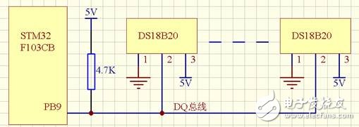
Figure 2 DS18B20 temperature acquisition circuit diagram
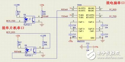
Figure 3 232 communication circuit diagram
3 software part3.1 Temperature Acquisition Subtask
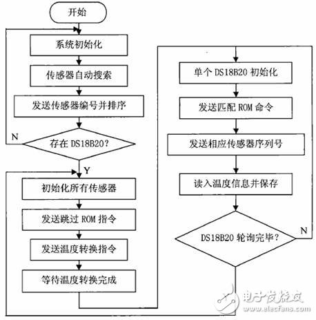
Figure 4 DS18B20 data collection flow chart
3.2 Fuzzy PID Control Subtask
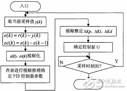
Figure 5 Flow chart of fuzzy PID algorithm
3.3 host computer interface
The upper computer interface is written in VB, which is convenient and practical, and easy to operate.
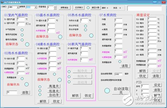
Figure 6 PC control interface
4 ConclusionThe system applies fuzzy PID temperature automatic control technology to aquaculture, and uses various water temperatures in the farm as the main controlled object. An automatic temperature control system based on fuzzy PID control theory is established. The whole system can effectively reduce consumption. To improve production efficiency, in line with the "energy saving and emission reduction" requirements put forward by the state, in line with the national economic development policy, has a very broad market application prospects.
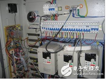
Figure 7 Debugging site one
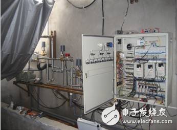
Figure 7 Debugging site II
Through the actual application test of the site for 3 months, it is currently running well and has achieved the original design goal.
Five And More Digits LED Display
Five And More Digits Led Display,Led Display Red Color,10 Segment Led Display,Yellow Segment Led Display
Wuxi Ark Technology Electronic Co.,Ltd. , https://www.arkledcn.com