Abstract: A variable gain amplifier (VGA), sometimes called a time gain control (TGC) amplifier, is a key component of a phase-space array ultrasound receiver. This article analyzes the impact of the VGA output reference noise and gain on the dynamic range and sensitivity of the ultrasonic pulse Doppler, and also analyzes how to use the MAX2037 eight-channel ultrasonic VGA to optimize these parameters, so that the typical receiver system The overall performance is optimal.
This article was also published in Maxim Engineering Journal, Issue 60 (PDF, 848kB).
Overview of Phased Array Receivers Before analyzing the impact of these key VGA parameters on the performance of the Doppler, we first review the basic components of a typical phased array ultrasound receiver channel and their working principles. For an in-depth understanding of phased array ultrasound receivers, please refer to Appendix A—Basics of Phased Array Ultrasound Systems. Typical receivers include LNA, VGA, anti-aliasing filter and ADC (as shown in Figure 1). The LNA amplifies the single-ended input signal of 1MHz to 15MHz from the sensor. The LNA has a gain of approximately 19dB and an active input impedance of 50Ω to 1kΩ.
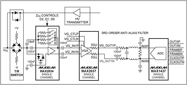
Figure 1. A typical phased array ultrasound receiver system composed of LNA, VGA, anti-aliasing filter and ADC
The amplitude of the signal at the input of the LNA may reach 0.5VP-P at the beginning of the receive cycle immediately following the transmit pulse. During the entire receiving process, the strength of the signal will gradually attenuate and eventually fall below the noise floor of the receiver. It is known that the attenuation rate of sound energy in the human body is about 0.7dB / cm-MHz (round trip is 1.4dB / cm-MHz), and the propagation speed of sound wave in the human body is 1540m / s (round trip is 13µs), so the attenuation value can be calculated. In the entire receiving cycle, the dynamic range required to process the signal is about 110dB, far exceeding the dynamic range of the actual ADC converter. Therefore, VGA (hereinafter referred to as "time gain control") is used to dynamically increase the receiver gain during the receiving period, so that the signal can adapt to the input dynamic range of the ADC. If you want to make the received signal adapt to the 70dB dynamic range of the 12-bit ADC, the gain range of the VGA is about 40dB. In the receiving link in Figure 1, a three-pole anti-aliasing filter can prevent the ADC from being affected by high-frequency noise and other signals above the maximum imaging frequency of 15MHz. A 12-bit ADC is usually used, and its operating frequency is between 40Msps and 60Msps.
VGA output reference noise and gain, and its impact on the PW Doppler. Standard 2D, gray-scale ultrasound imaging requires a dynamic range of approximately 40dB per phased array channel. However, since the received signal strength from blood may be much lower than the signal strength of surrounding tissues, pulsed Doppler imagers, such as spectral PW Doppler imaging and color Doppler imaging, require a dynamic range of up to 70dB, usually using large dynamic Range of 12-bit ADCs to improve the performance of Doppler receivers.
Designing a VGA that meets the ADC requirements of an ultrasound receiving system is quite difficult. It should be particularly pointed out that while maintaining a low output reference noise to maintain the dynamic range of the receiver, it can still provide sufficient gain to ensure reception under high TGC gain The machine has a low noise figure, which will be a difficult goal to achieve. When actually designing a VGA, lower output reference noise and higher maximum gain are usually contradictory aspects. In this case, VGA designers have to optimize and reasonably balance these VGA parameters to ensure that the overall performance of the receiver is optimal.
To better understand the impact of these VGA parameters on receiver performance, we consider two special cases. One situation is that the TGC gain is moderate or low, and the received signal is strong. In this case, the dynamic range of the receiver should be optimized. Another situation is that the TGC gain is the largest and the received signal is weak. The most important of the latter is that the receiver's noise figure should be optimized to maintain the receiver's sensitivity.
Effect of VGA output reference noise on receiver dynamic range (medium / low TGC gain) At medium / low TGC gain, VGA output noise is mainly VGA output reference noise. This noise should be much lower than the noise floor of the ADC, otherwise it will reduce the dynamic range of the ADC. Taking the ultrasound receiving system shown in Figure 1 as an example, the output reference noise of the MAX2037 VGA is about 22nV / , MAX1473 12-bit, 50Msps ADC for digital VGA output, with 31.7nV / Noise floor. Assume that the maximum input voltage of the ADC is 1.4VP-P, with an SNR of 70dB. In this example, if the anti-aliasing filter between the VGA and the ADC has a passband attenuation of 0dB, the effective SNR of the 70dB ADC will be reduced by 1.7dB to 68.3dB due to the VGA output reference noise. However, most anti-aliasing filters used in this type of system have some passband attenuation.
To ensure the stability of the system, many VGAs require some form of real output impedance to drive the filter. These impedances must be large enough to ensure that the filter capacitance is not infinitely small. This limitation usually introduces 3dB to 6dB of passband attenuation to the actual anti-aliasing filter. For the input of the ADC, the passband attenuation of the anti-aliasing filter further reduces the output reference noise and improves the dynamic range. If the passband attenuation is 6dB, the MAX2037's output reference noise will only reduce the ADC's SNR by 0.49dB.
It is easy to understand that if the VGA has an output reference noise much greater than the MAX2037, problems will occur. For example, when using an anti-aliasing filter with 6dB attenuation, the size is only 40nV / The VGA output reference noise (this value is about twice the MAX2037 output reference noise) will reduce the ADC's SNR by 1.5dB. For Doppler applications where imaging is difficult, this attenuation cannot be ignored. In addition, it is worth noting that the reduction in receive gain caused by the attenuation of the anti-aliasing filter will have a significant negative impact on the receiver noise figure, which we will describe in detail below.
The output reference noise of the MAX2037 is about half that of competing products. When used with a 12-bit ADC and passive anti-aliasing filter, the MAX2037 can provide higher gain, optimize dynamic range, and keep the receiver noise figure constant . Figure 2 shows the relationship between the MAX2037 output reference noise and gain.
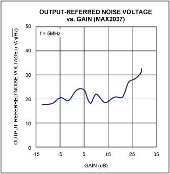
Figure 2. The noise of the MAX2037 is only half that of competing devices, while providing higher gain
The effect of the maximum gain of VGA on the receiver noise figure (at high TGC gain) At high TGC gain, the receiver needs to be optimized to improve the sensitivity of small signals. At this time, the total output reference noise of VGA and the noise floor of the ADC should be far Less than the sensor noise floor amplified at the input of the ADC.
Figure 3 is a simplified block diagram of an ultrasonic receiver. The figure shows the effect of the receiver gain before the ADC on the noise figure index. The receiver system uses a MAX2034 four-channel LNA with a gain of 19dB, a MAX2037 VGA with a maximum gain of 29.5dB, and an eight-channel 12-bit ADC MAX1437. It is also assumed that the anti-aliasing filter has a 6dB passband attenuation. Assuming that the impedance of the sensor is 200Ω, the thermal noise floor generated is VN = (4 × K × T × R × ΔF) ¼ or 1.8nV / . Assuming that the ZIN of the LNA is 200Ω, the thermal noise floor at the input of the LNA is about half of this value (0.9nV / ). Under typical LNA, VGA, and ADC noise specifications, the noise figure of the entire receiver system in this example is approximately 2.3dB. The noise floor of MAX1437 is 31.7nV / . When the TGC gain is maximum, the system before the ADC (including anti-aliasing filter) gain is 42.5dB. At this time, the noise of the ADC relative to the receiver input is only 0.237nV / In the total receiver noise figure of 2.3dB, the ADC only accounts for 0.18dB.
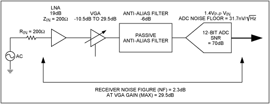
Figure 3. In the simplified block diagram of the ultrasound receiver, the effect of the previous gain of the ADC on the noise figure
What happens when the maximum gain of the VGA is low or the noise floor of the ADC is high? Figure 4 shows the effect of VGA gain on the small-signal noise figure of the typical ultrasonic receiver shown in Figure 3. Assuming that the receiver system uses a low-noise ultrasonic LNA with a gain of 19 dB and an anti-aliasing filter with an attenuation of 6 dB, we plot the noise figure curves when using two ADCs with different noise floors. The upper curve in the figure corresponds to MAX1437. The maximum input voltage of MAX1473 is 1.4VP-P, the SNR is 70dB, and the noise floor is about 31.7nV / ; The following curve corresponds to an ADC with a 2VP-P input and an SNR of 70dB. The noise floor of the ADC is about 45.2nV . The graph clearly shows the effect of receiver noise figure on these two different ADCs, and also shows the improvement of the receiver noise figure of the MAX2037 with a maximum gain of up to 29.5dB. When the maximum gain of VGA is low, it will increase the overall noise figure of the receiver when the TGC gain is maximum, and it will also reduce the sensitivity of small signal Doppler detection. Reasonable choice of low noise floor ADC, such as MAX1437, and VGA with higher maximum gain, such as MAX2037, can significantly improve the noise figure.
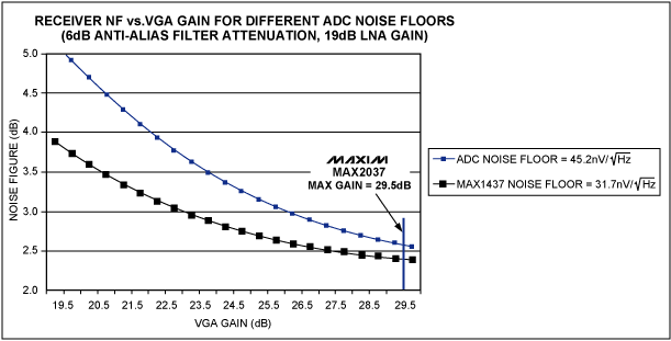
Figure 4. The relationship between the noise figure of the ultrasonic receiver shown in Figure 3 and the gain of the VGA
Conclusion It is necessary to pay attention to the VGA output reference noise, maximum VGA gain, anti-aliasing filter attenuation, and the influence of ADC noise on the receiver's dynamic range and noise figure, which helps optimize the sensitivity of the ultrasound receiver. The MAX2037 VGA is used to optimize and reasonably balance the output reference noise and the maximum gain so that it meets the performance requirements of 12-bit ADCs (such as the MAX1437), thereby obtaining the best ultrasound receiver specifications.
Appendix A—Basic Phased Array Ultrasound System Principle Block Diagram of Phased Array Ultrasound System Figure 5 shows the block diagram of a typical phased array ultrasound imaging system. All systems using this phased array scheme have 64 to 256 receive channels, and also have the same number of transmit channels. For simplicity, Figure 5 only depicts one transmit and receive channel.
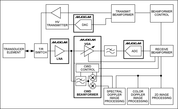
Figure 5. A transmit / receive channel in a typical phased array medical ultrasound imaging system
Basics of Ultrasound Transmission In order to obtain an ultrasound image, a phased array ultrasound system must generate N (here N = number of transmission channels) high-voltage transmission pulses with a certain delay. These pulses are used to excite various elements in the sensor array to produce focused acoustic emission (Figure 6).
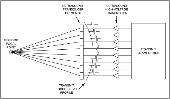
Figure 6. Focused ultrasound emission generated by a high-voltage emission pulse after a certain delay
Ultrasonic receivers use the discontinuity of the internal acoustic resistance of the human body to receive the reflected sound wave energy through the sensor, and then separately transmit it to each receiving channel of the system. These receiving channels first amplify the signal from the sensor, and then digitize them, as shown in Figure 7. Using the calculated time delay, the digitized signal is delayed and summed in the digital beamformer of the ultrasound system to generate a focused receive beamforming signal. The resulting digital signal can be used to generate two-dimensional (2D) and PW / color Doppler information.
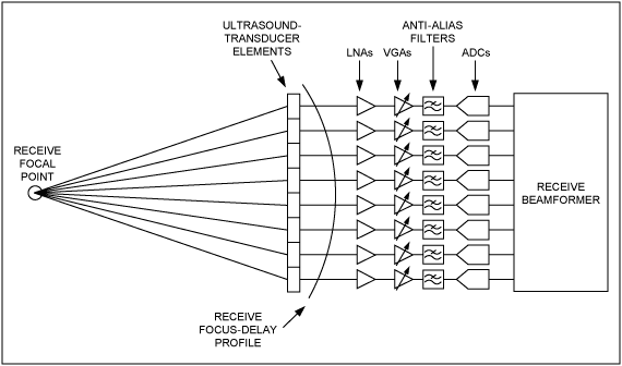
Figure 7. The receive channel in the ultrasound receiver system amplifies and digitizes the signals from various sensors
This article was also published in Maxim Engineering Journal, Issue 60 (PDF, 848kB).
Overview of Phased Array Receivers Before analyzing the impact of these key VGA parameters on the performance of the Doppler, we first review the basic components of a typical phased array ultrasound receiver channel and their working principles. For an in-depth understanding of phased array ultrasound receivers, please refer to Appendix A—Basics of Phased Array Ultrasound Systems. Typical receivers include LNA, VGA, anti-aliasing filter and ADC (as shown in Figure 1). The LNA amplifies the single-ended input signal of 1MHz to 15MHz from the sensor. The LNA has a gain of approximately 19dB and an active input impedance of 50Ω to 1kΩ.
Figure 1. A typical phased array ultrasound receiver system composed of LNA, VGA, anti-aliasing filter and ADC
The amplitude of the signal at the input of the LNA may reach 0.5VP-P at the beginning of the receive cycle immediately following the transmit pulse. During the entire receiving process, the strength of the signal will gradually attenuate and eventually fall below the noise floor of the receiver. It is known that the attenuation rate of sound energy in the human body is about 0.7dB / cm-MHz (round trip is 1.4dB / cm-MHz), and the propagation speed of sound wave in the human body is 1540m / s (round trip is 13µs), so the attenuation value can be calculated. In the entire receiving cycle, the dynamic range required to process the signal is about 110dB, far exceeding the dynamic range of the actual ADC converter. Therefore, VGA (hereinafter referred to as "time gain control") is used to dynamically increase the receiver gain during the receiving period, so that the signal can adapt to the input dynamic range of the ADC. If you want to make the received signal adapt to the 70dB dynamic range of the 12-bit ADC, the gain range of the VGA is about 40dB. In the receiving link in Figure 1, a three-pole anti-aliasing filter can prevent the ADC from being affected by high-frequency noise and other signals above the maximum imaging frequency of 15MHz. A 12-bit ADC is usually used, and its operating frequency is between 40Msps and 60Msps.
VGA output reference noise and gain, and its impact on the PW Doppler. Standard 2D, gray-scale ultrasound imaging requires a dynamic range of approximately 40dB per phased array channel. However, since the received signal strength from blood may be much lower than the signal strength of surrounding tissues, pulsed Doppler imagers, such as spectral PW Doppler imaging and color Doppler imaging, require a dynamic range of up to 70dB, usually using large dynamic Range of 12-bit ADCs to improve the performance of Doppler receivers.
Designing a VGA that meets the ADC requirements of an ultrasound receiving system is quite difficult. It should be particularly pointed out that while maintaining a low output reference noise to maintain the dynamic range of the receiver, it can still provide sufficient gain to ensure reception under high TGC gain The machine has a low noise figure, which will be a difficult goal to achieve. When actually designing a VGA, lower output reference noise and higher maximum gain are usually contradictory aspects. In this case, VGA designers have to optimize and reasonably balance these VGA parameters to ensure that the overall performance of the receiver is optimal.
To better understand the impact of these VGA parameters on receiver performance, we consider two special cases. One situation is that the TGC gain is moderate or low, and the received signal is strong. In this case, the dynamic range of the receiver should be optimized. Another situation is that the TGC gain is the largest and the received signal is weak. The most important of the latter is that the receiver's noise figure should be optimized to maintain the receiver's sensitivity.
Effect of VGA output reference noise on receiver dynamic range (medium / low TGC gain) At medium / low TGC gain, VGA output noise is mainly VGA output reference noise. This noise should be much lower than the noise floor of the ADC, otherwise it will reduce the dynamic range of the ADC. Taking the ultrasound receiving system shown in Figure 1 as an example, the output reference noise of the MAX2037 VGA is about 22nV /
, MAX1473 12-bit, 50Msps ADC for digital VGA output, with 31.7nV / Noise floor. Assume that the maximum input voltage of the ADC is 1.4VP-P, with an SNR of 70dB. In this example, if the anti-aliasing filter between the VGA and the ADC has a passband attenuation of 0dB, the effective SNR of the 70dB ADC will be reduced by 1.7dB to 68.3dB due to the VGA output reference noise. However, most anti-aliasing filters used in this type of system have some passband attenuation. To ensure the stability of the system, many VGAs require some form of real output impedance to drive the filter. These impedances must be large enough to ensure that the filter capacitance is not infinitely small. This limitation usually introduces 3dB to 6dB of passband attenuation to the actual anti-aliasing filter. For the input of the ADC, the passband attenuation of the anti-aliasing filter further reduces the output reference noise and improves the dynamic range. If the passband attenuation is 6dB, the MAX2037's output reference noise will only reduce the ADC's SNR by 0.49dB.
It is easy to understand that if the VGA has an output reference noise much greater than the MAX2037, problems will occur. For example, when using an anti-aliasing filter with 6dB attenuation, the size is only 40nV /
The VGA output reference noise (this value is about twice the MAX2037 output reference noise) will reduce the ADC's SNR by 1.5dB. For Doppler applications where imaging is difficult, this attenuation cannot be ignored. In addition, it is worth noting that the reduction in receive gain caused by the attenuation of the anti-aliasing filter will have a significant negative impact on the receiver noise figure, which we will describe in detail below. The output reference noise of the MAX2037 is about half that of competing products. When used with a 12-bit ADC and passive anti-aliasing filter, the MAX2037 can provide higher gain, optimize dynamic range, and keep the receiver noise figure constant . Figure 2 shows the relationship between the MAX2037 output reference noise and gain.
Figure 2. The noise of the MAX2037 is only half that of competing devices, while providing higher gain
The effect of the maximum gain of VGA on the receiver noise figure (at high TGC gain) At high TGC gain, the receiver needs to be optimized to improve the sensitivity of small signals. At this time, the total output reference noise of VGA and the noise floor of the ADC should be far Less than the sensor noise floor amplified at the input of the ADC.
Figure 3 is a simplified block diagram of an ultrasonic receiver. The figure shows the effect of the receiver gain before the ADC on the noise figure index. The receiver system uses a MAX2034 four-channel LNA with a gain of 19dB, a MAX2037 VGA with a maximum gain of 29.5dB, and an eight-channel 12-bit ADC MAX1437. It is also assumed that the anti-aliasing filter has a 6dB passband attenuation. Assuming that the impedance of the sensor is 200Ω, the thermal noise floor generated is VN = (4 × K × T × R × ΔF) ¼ or 1.8nV /
. Assuming that the ZIN of the LNA is 200Ω, the thermal noise floor at the input of the LNA is about half of this value (0.9nV / ). Under typical LNA, VGA, and ADC noise specifications, the noise figure of the entire receiver system in this example is approximately 2.3dB. The noise floor of MAX1437 is 31.7nV / . When the TGC gain is maximum, the system before the ADC (including anti-aliasing filter) gain is 42.5dB. At this time, the noise of the ADC relative to the receiver input is only 0.237nV / In the total receiver noise figure of 2.3dB, the ADC only accounts for 0.18dB. Figure 3. In the simplified block diagram of the ultrasound receiver, the effect of the previous gain of the ADC on the noise figure
What happens when the maximum gain of the VGA is low or the noise floor of the ADC is high? Figure 4 shows the effect of VGA gain on the small-signal noise figure of the typical ultrasonic receiver shown in Figure 3. Assuming that the receiver system uses a low-noise ultrasonic LNA with a gain of 19 dB and an anti-aliasing filter with an attenuation of 6 dB, we plot the noise figure curves when using two ADCs with different noise floors. The upper curve in the figure corresponds to MAX1437. The maximum input voltage of MAX1473 is 1.4VP-P, the SNR is 70dB, and the noise floor is about 31.7nV /
; The following curve corresponds to an ADC with a 2VP-P input and an SNR of 70dB. The noise floor of the ADC is about 45.2nV . The graph clearly shows the effect of receiver noise figure on these two different ADCs, and also shows the improvement of the receiver noise figure of the MAX2037 with a maximum gain of up to 29.5dB. When the maximum gain of VGA is low, it will increase the overall noise figure of the receiver when the TGC gain is maximum, and it will also reduce the sensitivity of small signal Doppler detection. Reasonable choice of low noise floor ADC, such as MAX1437, and VGA with higher maximum gain, such as MAX2037, can significantly improve the noise figure. Figure 4. The relationship between the noise figure of the ultrasonic receiver shown in Figure 3 and the gain of the VGA
Conclusion It is necessary to pay attention to the VGA output reference noise, maximum VGA gain, anti-aliasing filter attenuation, and the influence of ADC noise on the receiver's dynamic range and noise figure, which helps optimize the sensitivity of the ultrasound receiver. The MAX2037 VGA is used to optimize and reasonably balance the output reference noise and the maximum gain so that it meets the performance requirements of 12-bit ADCs (such as the MAX1437), thereby obtaining the best ultrasound receiver specifications.
Appendix A—Basic Phased Array Ultrasound System Principle Block Diagram of Phased Array Ultrasound System Figure 5 shows the block diagram of a typical phased array ultrasound imaging system. All systems using this phased array scheme have 64 to 256 receive channels, and also have the same number of transmit channels. For simplicity, Figure 5 only depicts one transmit and receive channel.
Figure 5. A transmit / receive channel in a typical phased array medical ultrasound imaging system
Basics of Ultrasound Transmission In order to obtain an ultrasound image, a phased array ultrasound system must generate N (here N = number of transmission channels) high-voltage transmission pulses with a certain delay. These pulses are used to excite various elements in the sensor array to produce focused acoustic emission (Figure 6).
Figure 6. Focused ultrasound emission generated by a high-voltage emission pulse after a certain delay
Ultrasonic receivers use the discontinuity of the internal acoustic resistance of the human body to receive the reflected sound wave energy through the sensor, and then separately transmit it to each receiving channel of the system. These receiving channels first amplify the signal from the sensor, and then digitize them, as shown in Figure 7. Using the calculated time delay, the digitized signal is delayed and summed in the digital beamformer of the ultrasound system to generate a focused receive beamforming signal. The resulting digital signal can be used to generate two-dimensional (2D) and PW / color Doppler information.
Figure 7. The receive channel in the ultrasound receiver system amplifies and digitizes the signals from various sensors
Surface Treatment DC Power Supply
Electrolysis Dc Power Supply,Charging Dc Power Supply,Motor Test Dc Power Supply,Experiment Dc Power Supply
Yangzhou IdealTek Electronics Co., Ltd. , https://www.idealtekpower.com