Research on Electronic Control Unit of Automobile Electric Power Steering System
1 Introduction
With the development of electronic control technology and its wide application in the automotive field, electric power steering (Electric Power Steering, referred to as EPS) has become more and more one of the hot spots of automotive electronic technology research. Compared with the traditional steering system, the EPS system has a simple structure and great flexibility, and can obtain ideal steering stability. It can dynamically adapt to changes in the driving situation of the car. It is comfortable, safe, environmentally friendly, energy-saving, and easy to maintain. It also fully demonstrates its superiority [1]. At present, electric power steering has partially replaced hydraulic power steering and has been widely used, such as Japan ’s Daihatsu, Mitsubishi, Honda Motor Company, the United States Delphi Automotive System Company, Germany ’s ZF Company, etc. have successively developed their respective EPS and assembled and used . Domestic research on EPS systems started late, and only Tsinghua University, Huazhong University of Science and Technology, Jilin University, Hefei University of Technology and other universities have carried out research on system structure design, system modeling and dynamic analysis, but are in theoretical exploration and experimental research. stage. Some domestic automobile manufacturers such as Chongqing Chang'an, Nanchang Changhe, Dongfeng, FAW and other universities are also in the preliminary stage of research and development, and have not reached the practical level [2].
2 The hardware composition and working principle of EPS system
2.1 EPS hardware composition
EPS is a power steering system that directly relies on electric power to provide auxiliary torque. The structure is shown in Figure 2-1. It is controlled by an electronic control unit (ECU) to provide power. The system is mainly composed of an electronic control unit, a torque sensor, and a rotation angle sensor. It consists of vehicle speed sensor (can be shared with other systems), DC motor, clutch, electromagnetic relay, deceleration mechanism and steering mechanism.
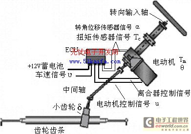
Figure 2-1 EPS system structure diagram
2.2 The working principle of EPS
When the vehicle ignition switch is closed, the ECU is powered on to start self-test of the EPS system. After the self-test is passed, the relay and clutch are closed, and the EPS system begins to work. When the steering wheel rotates, the rotation angle sensor and torque sensor on the steering shaft The measured angular displacement on the steering wheel and the torque acting on it are transmitted to the ECU. Based on these two signals and combined with the vehicle speed and other information, the ECU controls the motor to generate corresponding assistance to achieve the best control in the full speed range: when driving at low speed To reduce the steering force and ensure the car's steering is flexible and light. When driving at high speed, appropriately increase the damping control to ensure that the steering wheel operates steadily and reliably.
3 ECU system design based on PIC microcontroller
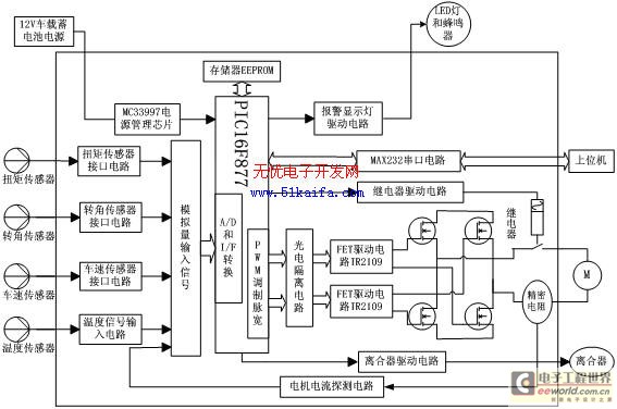
Figure 3-1 ECU system structure principle diagram
3.1 Working principle of ECU
The control core of the system is the PIC16F877 single-chip microcomputer, and the structure of the control unit is shown in Figure 3-1. The entire system is powered by the vehicle's 12V battery. When the ECU is working, the torque, rotation angle, vehicle speed, temperature and other sensors process the collected signals through the input interface circuit and send them to the corresponding port of the single-chip microcomputer. Analyze and process to determine the magnitude and direction of the boosting current, and issue pulse commands through the PWM port of the single-chip microcomputer and corresponding commutation control ports, and control the DC motor through the drive circuit and the H-bridge circuit. A current sensor is provided on the drive circuit of the motor, and the sensor feeds back the detected actual working current of the motor to the single-chip microcomputer through the current detection circuit, and then the single-chip microcomputer implements closed-loop control of the motor according to the corresponding control algorithm. If the EPS system works abnormally, the single chip computer will drive the EPS light to give an alarm prompt, at the same time disconnect the relay and clutch, exit the electric power assist working mode, and switch to manual manual assist mode [3].
3.2 Introduction to PIC16F877 MCU
This model is an 8-bit RISC structured single-chip microcomputer produced by American Microchip company. It has the characteristics of high-speed data processing (execution speed up to 120ns). The PIC16F877 has its own watchdog timer, EEPROM with 256Bytes, and FLASH of 8k Memory, 8-channel 10-bit AD conversion function, 2 pulse width modulation CCP modules, online programming debugging (ISP) function, wide voltage operation, high reliability. PIC16F877 has an 8-level deep hardware stack, each Byte bit in the RAM area can be addressed, and there are 4 dedicated bit manipulation instructions and 2 shift instructions.
3.3 Selection of DC motor
Brushless DC motors have obvious advantages in terms of control characteristics, efficiency, torque pulses, and manufacturing costs. This project uses permanent magnet brushless DC motor as the driving source.
3.4 Selection of torque and rotation angle sensors
This article uses the torque and position composite sensor of the Italian company BI. In addition to the torque signal, the sensor also provides the steering wheel position signal, which provides convenience for the development of the reset and damping logic.
3.5 Design of motor drive control circuit
The motor drive control circuit must be able to adjust the speed and output torque of the motor with high precision and quickly, so as to meet the requirements of EPS system real-time and reliability. The core control of the backward channel in this project uses pulse width modulation (PWM) to control the H-bridge circuit. There are many PWM control methods for DC motors. According to the actual needs of the motor work and the overall requirements of the system, this project uses a limited unipolar reversible PWM control mode. The main advantage is that it can avoid the same arm of the switch tube, and the operation reliability is high. No additional delay circuit is required, and the switching frequency is relatively high. It is especially suitable for the control of DC motors with high power, large moment of inertia, and high reliability requirements.
3.5.1 Motor drive circuit
The drive circuit of the motor mainly includes a FET bridge circuit, a FET base drive circuit, a current sensor and a relay on the motor drive circuit.
The FET bridge circuit is mainly composed of four high-power MOSFET power tubes, which require the power tube to have good switching characteristics, can withstand a large driving current, and have a long service life. According to the power parameters of the motor and the limit of the power tube Parameters and electrical characteristics, we use four identical N-channel IRFP250 power tubes to form an H-bridge circuit.
The FET base drive circuit selects the MOSFET special gate integrated circuit IR2109 as the core module. The chip is a single-channel, gate drive, high-voltage high-speed power device. It uses a highly integrated level conversion technology, which greatly simplifies the power of the logic circuit. The control requirements of the device, the upper tube is powered by an external bootstrap capacitor, which greatly reduces the number of driving power supplies, controls the volume of the circuit board, reduces the cost, and improves the system reliability [4].
The driving circuit is shown in Figure 3-2. The IN ends of the two IR2109 are the signal pulse input ends of the two power tubes driving the upper and lower arms of the H-bridge. They are connected to the two PIC16F877 microcontrollers through a 6N137 photocoupler with high-speed performance. PWM pulse output port; the two SD terminals are connected to an I / O port of the single-chip microcomputer respectively to control the motor stop operation; the HO and LO terminals of each chip are respectively connected to the power tube of the same bridge arm to control the motor speed; the VB terminal is passed The bootstrap diode UF1005 is connected to the + 12V power supply. In order to block all the voltages that are subjected to the special circuit, the diode UF1005 with ultra-fast recovery characteristics is selected here.
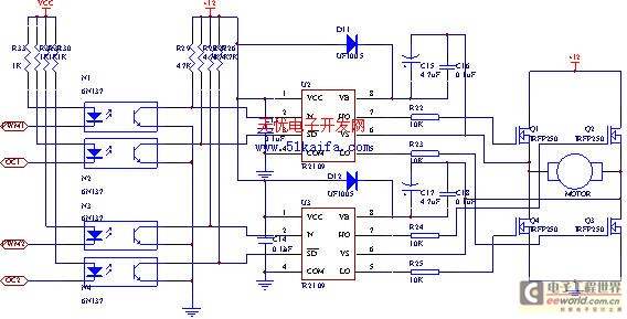
Figure 3-2 Motor drive circuit
3.5.2 Motor current sampling circuit
The system has two uses for current sampling, one is to provide protection for the motor; the other is to feedback the armature current signal through the current sensor, so as to perform closed-loop control of the armature current. Standard resistance is a commonly used current sensor. Due to its simple and reliable, stable resistance, high accuracy, good frequency response, and the output voltage is directly proportional to the current flowing, it is widely used in PWM systems. Standard resistors are generally made of manganese copper or silicon manganese copper. In the sampling circuit, AD626 is used to amplify the sampling signal by 10 times to the corresponding port of the single-chip microcomputer. The specific circuit is shown in Figure 3-3.
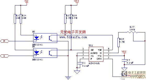
Figure 3-3 Motor current sampling circuit
3.6 Relay control circuit
As shown in Figure 3-4 below, after the CPU control signal is output through the CPU port PSP0, the switch Q1 is turned on and drives the power transistor Q12 to energize the relay and close the node. After the relay node is closed, it can supply power to the motor and clutch. The high and low level signals output by the CPU respectively control the closing and opening operations of the relay.
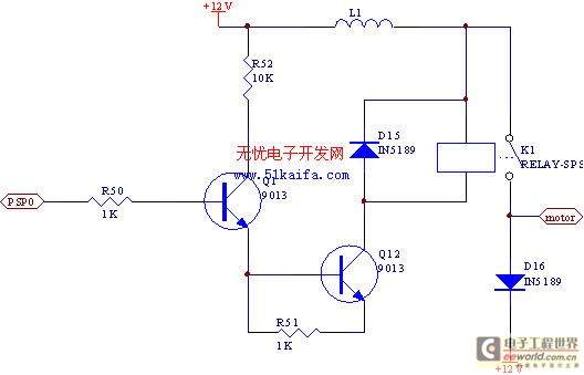
Figure 3-4 Relay control circuit design
4 Conclusion
In this paper, based on the analysis of the principle of the EPS system and the power control process, the hardware circuit of the EPS control system is researched and designed, and a restricted unipolar reversible PWM control mode is used to control the DC motor; In the steering system, the control method of low voltage, low speed, high current permanent magnet brushless DC motor. The method of sampling the motor current using a precision resistor realizes the closed-loop control of the output torque of the DC motor. After completing the hardware circuit design and software programming, a bench test was conducted on the EPS system according to the predetermined assist characteristic curve. The test results show that the real-time signal acquisition of the electronic control unit is high, and the followability of the motor closed-loop control is relatively Well, the whole system has good electric power-assisted characteristics, and the anti-interference ability and reliability of the hardware part are very high.
Innovation
1. Adopt PIC16F877 single chip microcomputer as the core of electronic control unit.
2. Use the restricted unipolar reversible PWM control mode to control the DC motor.
Modern luxury hotels, commercial centers and homes are more and more high demand for lighting systems. The DALI light led driver series promoted by MOSO are complying with the IEC62386/IEC60929 standard. And it can be connected to any device that conforms to DALI protocol in one circuit control.


The Dali LED Driver is designed specially for the project requiring DALI control; it is approved by CE, TUV, ENEC, and DALI mark on the label.
Dali LED Driver,Dali Dimmable LED Driver,Dali Street Light LED Driver,Dali Flood Light LED Driver
Moso Electronics , https://www.mosoleddriver.com