Figure 4-6 is 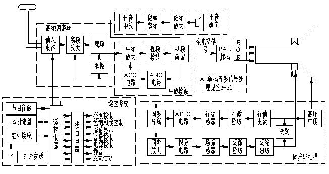
This article refers to the address: http://
High frequency tuner
The high frequency tuner, also known as the high frequency head, has the function of selecting channels, amplifying signals, and changing frequencies. The function of the antenna and the input circuit is to select the weak TV signal of the channel to be received, and to perform selective amplification by the high frequency amplifier, and then mix the sine wave with the higher frequency of the local oscillator to obtain the intermediate frequency signal. The high-frequency tuner has good selectivity and can suppress image (up to 2 times higher than the signal frequency) interference, IF interference and other interference signals. The coupling of the isolation mixer to the antenna prevents the local oscillator signal from radiating out through the antenna and interfering with other receivers.
The mixer converts the received RF TV signals of different channels into a fixed frequency intermediate frequency signal. In China, the image intermediate frequency is 38 MHz, and the first audio intermediate frequency is 31.5 MHz. The latter intermediate frequency amplifier can obtain good selectivity and high gain due to the fixed frequency. The total gain of a typical high frequency tuner is approximately 20 dB. 
2. Middle and detection
The intermediate frequency amplifier amplifies the image intermediate frequency signal and the first audio intermediate frequency signal sent by the high frequency tuner, and the main task is to amplify the image intermediate frequency signal, and the amplification factor of the audio intermediate frequency signal is small, so the intermediate frequency amplifier is often referred to as an image. put. The center amplifier is the main amplification unit of the entire TV receiver, requiring a gain of more than 60 dB.  In order to adapt to the vestigial sideband transmission and suppress interference, the mid-amplitude characteristic curve is specially shaped, which is formed once by the surface acoustic wave filter (SAWF). 
The first task of the video detector is to detect the video image signal from the intermediate frequency image signal, generally using large signal detection or envelope detection. The second task of the video detector is to generate a second audio intermediate frequency signal of 6.5 MHz from the image intermediate frequency and the accompanying intermediate frequency difference using the nonlinearity of the diode. 
The output signal of the detector is to be supplied to the PAL encoder, the synchronous separation circuit, the automatic gain control (AGC) circuit, and the sound center amplifier circuit, so video preamplification is first performed to enhance its load capacity. Amplifying from the antenna to the video preset is called a common channel (image and sound). 
The function of the automatic noise suppression (ANC) circuit is to automatically suppress the interference pulse so as not to affect the normal operation of the synchronous separation circuit. A common method is to separate the interference pulse, and then superimpose it on the original signal to cancel the interference pulse. The function of the  automatic gain control (AGC) circuit is to detect a DC voltage that varies with the input signal level to control the gain of the IF amplifier and the high frequency amplifier to keep the video detection output amplitude substantially constant. 
3. Sound channel
The 6.5 MHz second audio IF signal taken out from the video preamplifier is sent to the audio IF amplifier. After amplification and limiting, it is sent to the discriminator for frequency detection, the audio signal is detected, and then low-level, and finally at the speaker. TV sound.
4. PAL decoder
The PAL decoder is detailed in Section 3.3.6 PAL decoder and the PAL decoder block diagram shown in Figure 3-21.
5. Synchronization and scanning circuits
The video image signal is sent to the synchronous separation circuit after the interference pulse is cancelled by the ANC circuit, and the composite synchronization signal is separated. After the composite sync signal is amplified, the field sync signal is separated by the integration circuit, and the field sync signal is then controlled to synchronize the sawtooth signal generated by the field oscillator with the transmitting end. The field sawtooth signal is amplified by the field push stage and the field output stage, and the field deflection coil is present. The field scan current is generated. 
In order to improve the anti-interference of the line scanning circuit, modern television receivers use an automatic frequency phase control (AFPC) circuit. The composite sync signal is directly added to the phase detector of the AFPC circuit and compared with the line oscillating signal. If there is a difference between the frequency and phase of the two, a voltage proportional to the error is output to control the frequency and phase of the line oscillator to be synchronized with the originating terminal. Due to the action of the low-pass filter in the AFPC circuit, the anti-interference of the line synchronization is enhanced.
The row oscillating signal synchronized with the transmitting terminal is amplified by the row driving stage and the row output stage to generate a line deflection current in the row deflection coil. The line scan reverse pulse is boosted and rectified to obtain the voltage required for the high voltage, medium voltage, and video amplification circuits (combined with the PAL decoder primary color matrix) required by the picture tube. The auxiliary circuits of the  color picture tube include convergence, geometric distortion correction, white balance adjustment, color purity adjustment, degaussing, etc. 
Welcome to reprint, this article from the electronic enthusiast network ( http:// )
6. Remote control system
The remote control system consists of a local keyboard, program memory, infrared remote control transmitter, infrared receiver, microcontroller and interface circuit. 
The keyboard of the machine is located on the TV panel, and the user operates through the keyboard of the machine to complete the channel selection, preset or various functions control of the TV. 
The function of the keyboard on the infrared remote control transmitter is basically similar to that of the local keyboard. The difference is that it can be away from the TV set and control the TV set by infrared light command signal. When a key of the infrared remote control is pressed, the encoder in the remote controller outputs a corresponding binary code and modulates it on the 38 kHz carrier, and then modulates the infrared light-emitting diode to become an infrared remote command signal. The infrared photodiode installed in the infrared receiver behind the TV panel receives the infrared remote control command signal, and then obtains the binary code of the instruction by amplifying, detecting and shaping, and sends it to the microcontroller for decoding to identify the type of control and The content, according to which the corresponding signal is sent, through the interface circuit to adjust the TV.
The program memory uses an electrically erasable programmable read only memory (EEPROM) for storing tuning voltage data of several channels, various function control parameters, etc., and also stores last viewed television program information, including channel number, TV/AV status, Volume, brightness, contrast, color saturation, etc. 
The microcontroller is the core of the remote control system, consisting of 8 bit arithmetic and logic operators, various registers, voltage or frequency synthesizer, RAM (data memory), ROM (cured all channel selection, presets and various functions control) Program), I/O port, instruction decoder, bus, master clock, etc. The user's remote control commands, such as channel selection, preset, volume, brightness, etc., are executed together with the peripheral circuits. 
The interface circuit controls the code of various functions sent by the microcontroller, decodes, D/A converts to 64-level analog control voltage, and then controls volume, brightness, color saturation, power supply, and the like. 
trumpet is the world's first ever fully Plastic Trumpet - a fully functioning Bb trumpet, designed in the UK for musicians by musicians. It comes in its own, smart gig bag along with a 3c and 5c mouthpiece. Authentic trumpet is a truly authentic musical instrument that has sparked a revolution in the way the music industry thinks about trumpets. trumpet follows in the footsteps of its sister instrument, pBone, the world's best selling trombone. Innovative trumpet is the only trumpet with a fully plastic valve system, which we have designed and developed to create unrivalled lightness, durability and sound quality. Accessible trumpet is less than half the weight of a brass trumpet due to the plastic material throughout the whole instrument, so it's ideal for the younger player and for all those who may have difficulty with the weight and balance. Mouthpiece We have designed fully plastic mouthpieces especially for the trumpet. Each instrument comes with both a 3c and 5c trumpet mouthpiece, you can also use any standard metal trumpet mouthpiece in the trumpet. Adjustable tuning slides The all-plastic main, first and third valve tuning slides give you the flexibility of tuning that you would expect of any trumpet. BioCote Protection For the first time in a musical instrument, trumpet incorporates patented anti-microbial technology from BioCote, which provides the highest standards of protection. Pitched in Bb4.75 inch Bell Unique fully plastic valve system One piece patented lead pipe All plastic water key Adjustable main tuning slide Adjustable 1st and 3rd valve tuning slides Weighs just 500gWorks with any standard mouthpiece Includes fabric carry bag. pTrumpet is less than half the weight of a brass trumpet due to the plastic material throughout the whole instrument, so it`s ideal for the younger player and for all those who may have difficulty with the weight and balance. Its unrivaled price enables everyone to enjoy the quality of an equivalent metal instrument at a third of the cost. Happy in the hands of the world`s seasoned professionals, pTrumpet is also the perfect starter instrument. pTrumpet is the only trumpet with a fully plastic valve system, which we have designed and developed to create unrivalled lightness, durability and sound quality. Our patented lead pipe technology ensures a vibrant and focused sound. It is tough, taking knocks and bumps in its stride – thanks to its precision plastic engineering. Mouthpiece We have designed fully plastic mouthpieces especially for the pTrumpet. Each instrument comes with both a 3c and 5c pTrumpet mouthpiece, you can also use any standard metal trumpet mouthpiece in the pTrumpet. Functional Features: Precision made high quality Bb plastic trumpet 5¡± One Piece Bell, 0.459" Bore 5¡± Weight: Approx. 500g Extremely robust and sturdy ABS construction Adjustable 1st,2nd and 3rd valve tuning slides Adjustable main tuning slide 2 Water keys (main tuning and 3rd valve tuning slides) Conventional top sprung valves with interchangeable springs Rugged one piece moulded valve block Unique twist and lock quick release top and bottom valve caps Valves can be lubricated by any normal quality synthetic oil 5 bracing points from bell section to valve block and leadpipe section Reinforced mouthpiece receiver - accepts any standard metal mouthpiece Conventional design with smooth comfort hold styling
Music Instrument, Music Equipment, Plastic Trumpet, Traditional Suona
Donguan Bronco Filter Co., Ltd , http://www.broncofilter-cn.com