At present, there are a variety of chord control chips in the mobile phone market, and more are used in Japan's Yamaha, Taiwan's Winbond and Wanghong, mainland China's Zhongxingwei and Zhiduowei. Each company's chord chips have their own characteristics, of which the C520 can support the national musical instrument, so the C520 is used for chord music control.
This article refers to the address: http://
2 C520 chord chip
The C520 is a chord chip from Shanghai Zhiduo Microelectronics Co., Ltd., which is designed to provide crisp and realistic music ringtones and rich game sound effects for mobile phones. The chip integrates a 64-chord, 16-tone color wave table and 21 Chinese folk music, MIDI synthesizer with 3D stereo surround enhancement, MIDI GM preset ROM, 16-bit high-performance audio digital-to-analog converter and 2/4-bit ADPCM decoding. And other functions.
2.1 chip features
Compared to other mobile phone chord chips on the market, the C520 has the following features:
1 The input MIDI signal can be synthesized by the on-chip music synthesizer, or the input ADPCM signal can be demodulated by the ADPCM demodulator, and then the waveform is output through the built-in DAC.
2 Integrated high-quality MIDI GM sound library with a capacity of up to 3 Mb; provides a national musical instrument sound library outside the GM sound library, supports more than 20 national musical instruments such as erhu, guzheng and cymbal; supports multi-timbral and polyphonic – at the same time Supports 16 tones and 64 polyphony.
3 With multiple function ports, it can support mobile phone vibration drive and LCD backlight drive. It can be used to play music sync PWM to control colorful lights.
4 The interface with the host can be a parallel interface or a serial interface; allows the chip to operate in the DAC input mode, accept input data compatible with the universal serial DAC data format; integrate FIFO with different input data on-chip; typical operating current in standby mode Less than 50 μA.
2.2 Functional unit
The entire chip consists of an IOU (I/O Interface Unit), SG (Music Synthesizer), ADEC (ADPCM Demodulator), TG (Clock Module) and ANALOG (Logical) modules.
The IOU completes the interface with the external CPU, controls the internal FIFO and other functional interfaces of the chip; the MIDI data forming the music and the control commands of the external CPU to the chip are also sent through the registers in the IOU. The SG module synthesizes the music from the MIDI data of the IOU's FIFO. The ADEC receives the compressed PCM data, decodes according to the corresponding control signal, and outputs the decoded 16-bit PCM code to the DSP unit of the SG. The TG multiplies the input clock and generates an internal clock. The ANALOG includes a DAC and an AMP that low-pass filters and power-amplifies the output signal of the DAC. The internal structure of the C520 chip is shown in Figure 1.
3 applications
3.1 Typical circuit
The control CPU uses Samsung's 32-bit RISC chip S3C4510B. The chip is specifically developed for embedded Ethernet applications. The core is ARM7TDMI and supports the high code density THUMB instruction set for price and power sensitive applications.
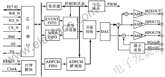
Figure 1 C520 internal structure block diagram
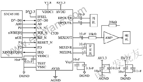
Figure 2 typical application circuit
The C520 and S3C4510B can be parallel or serial, but the parallel interface has faster data transfer speed than the serial interface, so parallel interfaces are used in this design. The chip application circuit is shown in Figure 2.
In this circuit, the CS_N of the C520 is controlled by the I/O P0 of the S3C4510B. In fact, if the chip select signal line is sufficient, you can select any one of the ROM/SRAM/Flash chip select signals Nrcs[5:0] in S3C4510B, which can save 1 GPIO; similarly, if If you do not want to control the C520 reset, you can connect its reset signal to the reset line nRESET of S3C4510B, so that S3C4510B and C520 will be reset at the same time of power-on; C520 PD pin is the low-power state control pin, "1" is normal working state. “0†is the low power consumption state; C520 IRQ pin is the interrupt output pin, which can be connected to the external interrupt request signal pin XINTREQ of S3C4510B.
3.2 Chip Initialization
The initialization of the C520 is very simple, including:
1 Set the PLL division ratio according to the external clock. The PLL divider ratio is determined by the register CLOCK (read: 10h/write: 11h) and the register Master Clock (read: 18h/write: 19h). The internal clock frequency fsys=fclock·(DN+1)/(DM+1). DM is the register CLOCK[4:0], DN is the register Master clock tuning[5:0], fclock is the external input clock, and the internal system clock frequency fsys must be set between 48 MHz and 50 MHz.
2 Open the analog module and write 0 to bit 3 of the register Analog Power Down (read: 66h/write: 67h).
3 Set Analog Select and select the analog function according to the register Analog Select (read: 60h/ write: 61h).
3.3 Playing MIDI music files
The C520 can play MIDI files in MIDI FORMAT 0 and MMD formats.
The ASCII FORMAT 0 file starts with 4 bytes of data with the ASCII value "MThd", and the MMD file starts with 4 bytes of data with the ASCII value "MMhd". The process of sending MIDI data in these two formats by ARM is different, and it is distinguished according to the 4-byte data at the beginning of the file before transmission.
Send a MIDI file in MIDI FORMAT 0 format and send all the data in the file.
The MMD format file can be divided into four blocks, each of which has an 8-byte header data portion at the beginning. The first 4 bytes of the ASCII code value of the first block header data is "MMhd", the first 4 bytes of the ASCII code value of the second block header portion are "MMly", and the first 4 bytes of the ASCII code value of the third block header data portion are "MMdd". The ASCII code value of the first 4 bytes of the 4th header data portion is "MMex". The 5th, 6th, 7th, and 8th bytes of each header data are the length of the data (excluding the header data), the 5th byte is the low byte, and the 8th byte is the high byte. The hexadecimal data consisting of bytes plus the header data length of 8, is the length of the data. The header data of the MMdd block data is followed by the compressed MIDI data; the MMly block data is dedicated data for karaoke, and the block is not required to be transmitted when playing MIDI; Mmex is an extended block.
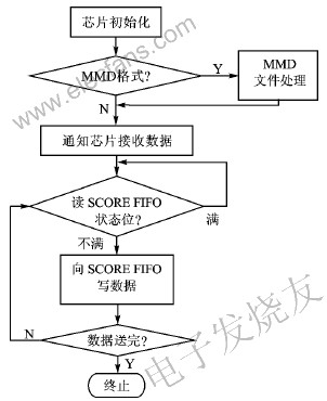
Figure 3 shows the process of playing MIDI files
When the MIDI data of the MMD format is transmitted to the C520, the MMhd block is transmitted first, and then the MIDI data portion of the MMdd block (ie, the block name and the block length portion of the block) is transmitted, and the MMly block is not sent.
Figure 3 shows the flow of playing a MIDI file.
Conclusion
This paper introduces the mobile phone chord chip C520 of Zhiduo Company, and gives its principle and internal structure diagram. The Samsung RISC chip S3C4510B is used as a controller to realize the playback of chord music. The detailed circuit schematic and the process of playing MIDI music files are given in the paper, which can be used as a reference for the application of chord chips in mobile products.
Ups Battery Pack,Ups Battery,Lithium Ups,Rechargeable Ups Battery
ZHEJIANG TIANHONG LITHIUM-ION BATTERY CO.,LTD , http://www.tflbattery.com