Abstract: In order to replace the traditional and complicated automobile wiring harness, the automotive CAN bus came into being. Based on CAN bus and combined with 51 series single chip technology, the CAN bus multiplex transmission system of automobile headlights was researched and developed. According to the overall structure, the CAN bus transmission node software design is designed, and the parallel port CAN adapter card is designed. By writing a dynamic link library (DLL), the upper layer application software provides a read/write function interface, which realizes the communication between the upper computer and the lower computer. . This design greatly simplifies the traditional wiring harness, greatly improves the reliability, and effectively saves the wiring harness installation space.
Key words: headlight; CAN bus; multiplex transmission system; single chip microcomputer
0 Introduction The CAN (Controller Area Network) data bus is a car LAN suitable for automotive environments. It belongs to one of the multiplex systems and was developed by Bosch in Germany in the early 1980s to solve the data exchange between numerous control units and test instruments in modern automobiles. letter of agreement. At present, in the field of automotive design, CAN has almost become a technical means that must be adopted, especially in Europe, such as Mercedes-Benz, BMW, Porsche, etc., using CAN bus to realize the data between the internal control system of the vehicle and the detection and execution agencies. Communication. In addition, the US automaker has gradually transitioned the controller networking system from Class 2 to CAN. The CAN international standard only defines the physical layer and the data link layer. In practical applications, some manufacturers and companies have defined corresponding application layer specifications to make the application of CAN more extensive and reliable.
The CAN signal transmission medium is a common twisted pair cable with a communication rate of up to 1 Mbps/40 m and a direct transmission distance of 10 km/5 Kbps. The signal transmission of CAN adopts short frame structure, and the number of valid bytes per frame is 8, so the transmission time is short and the probability of interference is low. Because of its CRC-16 check mode, the bit error rate is only 3×. 10-5. When the node is seriously wrong, it has the function of automatically shutting down to cut off the connection between the node and the bus, so that the communication of other node machines on the communication line is not affected, and has strong anti-interference ability. Controller Local Area Network (CAN) belongs to the field bus field and is a serial communication network that effectively supports distributed control or real-time control.
As a microcontroller communication in the automotive environment, CAN exchanges information between the vehicle's electronic control unit ECUs to form an automotive electronic control network. For example, the engine management system, the gearbox controller, the instrumentation equipment, and the electronic trunk system are all embedded in the CAN control device. However, the CAN bus multiplex system has not been applied to automotive headlamps. The traditional automotive system wiring has a large workload. Once the line is found to be faulty, the diagnosis work is very difficult. At the same time, due to the long data transmission line, the transmission speed is reduced, and the reliability and real-time performance are poor. As one of the most promising fieldbuses, CAN bus technology has become a new choice to solve this problem by virtue of its high reliability, strong adaptability to the environment, outstanding error correction capability and high cost performance. Based on this research background, this paper researches and develops a car headlight multiplex transmission system based on CAN bus.
1 CAN controller SJAl000
1.1 SJAl000 hardware structure and function CAN communication protocol is mainly completed by CAN controller. The CAN controller is mainly composed of a CAN bus protocol part and a microcontroller interface part. Different types of CAN bus communication controllers realize the structure and function of some parts of the CAN protocol circuit, and there are some differences with the structure and mode of the interface part of the microcontroller. SJAl000 is a stand-alone CAN controller and is the first generation of new controllers from PHILIPS. Support CAN 2.0B protocol.
The main features of SJAl000 are as follows:
Device pin and electrical characteristics are compatible with PCA82C200; clock frequency is 24 MHz; support CAN protocol 2. O standard bit rate up to l Mb / s; support 11-bit identifier and 29-bit identifier; extended receive buffer (up to 64 B, PCA82C200 only 20 bytes); interface to different microprocessors; Programmable CAN driver output.
SJAl000 has two modes of operation: basic mode and Peli mode. The basic mode is in compliance with the CAN protocol 2.0A standard and is compatible with the PCA82C200. Set the most significant mode select bit (CDR.7) of the Clock Divider (CDR: Clock divider Register) to switch between Basic mode and Peli mode.
1.2 CAN transceiver 82C250 hardware structure and function 82C250 is the interface between the CAN controller and the physical bus, initially used mainly in automotive high-speed control applications. It provides differential transmit capability to the bus and provides differential reception capability to the CAN controller.
The main features of the 82C250 are as follows: compatible with the ISO/DISll898 standard; high speed (up to 1 Mb/s); instantaneous interference against automotive environments, protection of bus capability; and reduction of radio frequency interference (RFI) slope (slope) Control; thermal protection; short circuit between protective battery and ground; low current standby mode; one node will not affect the bus when power is lost; there may be 110 nodes connected.
2 system hardware circuit diagram design
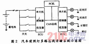
2.1 Schematic diagram of car headlights The schematic diagram of the traditional power supply line of the car headlights and the multi-channel bus transmission system of the car headlights are shown in Figure 1, Figure 2. 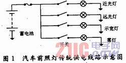
This article refers to the address: http://
2.2 System hardware circuit schematic The design of the CAN intelligent node circuit diagram is the core of the system. The detailed CAN node hardware circuit design is given below.
Fig. 3 is a schematic diagram of the hardware circuit of the CAN bus multiplex transmission system of the automobile automobile headlight. As can be seen from the figure, the circuit is mainly composed of three large blocks. The first block is the switch circuit part of the headlight, which mainly includes the microcontroller 89C51 single chip microcomputer, the independent CAN communication controller SJAl000, the CAN bus transceiver 82C250; the second block is the upper computer, including the CAN bus adapter card and the data display part. The third block is the electrical circuit part of the headlight, which mainly includes the microcontroller 89C51 single chip microcomputer, the independent CAN communication controller SJAl000, and the CAN bus transceiver 82C2 50. It should be noted that the system uses four light-emitting diodes instead of the low beam, high beam, width lamp and fog lamp in the specific automobile headlight. 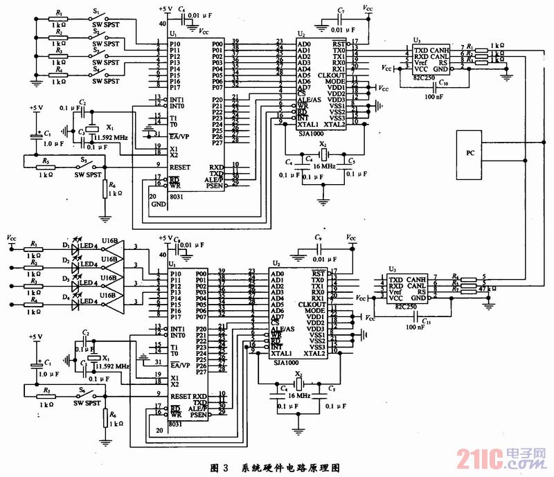
The microprocessor 89C51 is responsible for the initialization of SJAl000, and realizes communication tasks such as receiving and transmitting data by controlling SJAl000. SJAl000's ADO~AD7 are connected to the P0 port of 89C51, and SJAl000 is connected to P2 of 89C51. O, P2. When O is 0, the CPU off-chip memory address can be selected as SJAl000, and the CPU can perform corresponding read/write operations on SJAl000 through these addresses. SJAl000, ALE is connected to the 89C51 pin, connected to 89C51, 89C51 can also access SJAl000 through the interrupt mode.
The interface between the 82C250 and the CAN bus uses certain safety and anti-interference measures. The CANC and CANL pins of the 82C250 are each connected to the CAN bus through a 5 Ω resistor. The resistors can be used to limit the current to protect the 82C250 from overcurrent. Two small capacitors of 30 pF are connected in parallel between CANH and CANL and ground, which can filter out the interference on the bus and the ability to prevent electromagnetic radiation. A slope resistor is connected to the Rs pin of the 82C250. The resistor size can be adjusted according to the bus communication speed, generally 16 to 140 kΩ.
2.3 The choice of microprocessor The real-time nature of the automotive electronic control system is based on the high-speed computing function of the microprocessor, so the choice of the microprocessor is an important part of the system design, compared with the general electronic equipment, the car The microprocessor of the electronic control system is characterized by frequent handling of a large number of input and output signals, and high precision and real-time control, so it is necessary to be able to perform multiple independent operations at the same time. To meet these requirements, microprocessors must have features such as high-speed computing, high-speed real-time input and output, and multiple interrupt responses. Since the control functions of the general electronic computer electronic control system are relatively simple, an 8-bit microprocessor is mainly used in most electronic control units (ECUs). In the choice of micro. On the processor, not only must we pay attention to meeting the technical requirements, but also comprehensively consider the cost and practical factors, and should not unilaterally pursue the high speed and high number of bits of the microprocessor.
This research is to deal with the logic signal of the button switch, the requirements of the microprocessor core control CPU is not high, the choice of AT89C51 can meet the requirements.
3 Software design of car headlight CAN bus multiplex system The software design of multiplex system includes CAN node initialization, CAN message transmission and reception, and PC and CAN adapter card communication.
3.1 Initialization System node initialization includes: self-test, CAN communication initialization, A/D initialization, various system flag initialization, and watchdog initialization. The initialization process of the 89C51 CAN controller is shown in Figure 4. 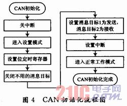
3.2 CAN sub-node transceiver software design The main function of the sub-node is to realize the collection of the button signal, and in response to the command of the main control node, send the detection point information to the main control node through the CAN bus. In software design, the child node adopts the command-one response mode, that is, waits for the command → analyzes the command type → sends back the corresponding data.
After the power-on reset, the child nodes in the system mainly work as follows:
(1) Initializing the system;
(2) issuing a join request to the master node;
(3) The master node accepts the request and gives the child node a network number;
(4) waiting for the master node command;
(5) According to the command, the relevant data of the monitoring point is sent to the main control node through the CAN bus.
Therefore, the main flow of the child node is shown in Figure 5. 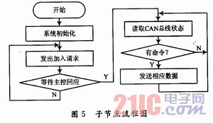
3.3 Main control node software design The main control node software adopts event-driven mode, and the event signal is generated by various interrupt signals; after entering the interrupt processing program, the CPU only judges the event type, sets the corresponding event flag bit, and does not do the event. Any processing; the main control node main program will cyclically read the event flag and transfer it to the corresponding event handler.
The master node has two modes of operation. One is that there is a host computer in the system, the host computer acts as a command issuing point, and the master node is in a passive control mode. At this time, the work of the master node is to receive the command of the host computer through RS 232, analyze the destination node of the command, and send the command to the destination node through the CAN network; meanwhile, the master node detects the node data on the CAN network, and the node is The sent data is sent to the host computer via RS 232; the above process is repeated until the working mode changes. In this way, the main workflow of the master node is shown in Figure 6. 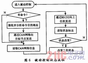
When there is no upper computer or the upper computer sends out the system command in the system, the main control node enters the active control working mode. In this state, the command sender is the master node, and the master node can query the working state of each node through the timer event; respond to the keyboard event, and issue a command to the target node or respond to the corresponding child node according to the command input by the user. The data of the child node is displayed by the LED light.
Between the two working modes, the command can be issued by the upper computer, the user can input the command through the keyboard, and the main control node can query the working state of the upper computer abnormally (for example, in the passive state, the upper computer has no command for a long time) and the like.
3.4 PC monitoring system design The PC monitoring system is based on C++ design, which can simultaneously collect and store multiple data, and design a graphical monitoring display. Monitoring system features include:
(1) Issue an online or offline command to the master node to switch the working state of the node;
(2) Sending a node query command periodically, querying the working status of the child node, and updating the system node table;
(3) According to the needs of the user, periodically send a read command to the monitoring node, obtain the monitoring data of the node, and save the data to form a monitoring data file;
(4) Display the monitoring curve in a graphical manner.
The upper computer system also includes the data analysis function, in which the algorithm interface is designed; the system user can write his own algorithm library, and the system can call the user algorithm library to further analyze the collected raw data.
4 Conclusion Because CAN bus has strong anti-interference ability, the system is very reliable in using field data communication, and the communication quality and distance can be further improved by CAN repeater. With the improvement of the performance of the CAN bus chip and the reduction of the price, it is gradually applied to ordinary cars, and it also provides conditions for its application in agricultural machinery. Studying the application of CAN bus in agricultural machinery such as tractors is of great significance for improving the performance and economy of agricultural machinery and promoting the development of agricultural mechanization in China.
LED point light source is a new kind of energy conservation and environmental protection decorative light, using LED cold light source, the built-in microcomputer chip, can be arbitrary programming control, multiple synchronous change, monochromatic changes can also be realized synchronous colorful gradient, jump, scanning, running water light color change effect and multiple LED point light source form a lattice screen.All kinds of pictures, text and animation effects can be changed. It is a supplement of linear light source and flood lighting, which can meet the design requirements of the point line surface.


Product size

Led Point Lamp,Blue Point Led Lamp,Led Point Ovale,Led Blue Point
Jiangsu chengxu Electric Group Co., Ltd , http://www.satislighting.com