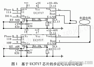
The uc3717 chip from uNI_rRODE is designed for low-power bipolar stepper motor control, making it ideal for applications that require micro-step precision. It offers an easy interface with microcomputers and is commonly used in systems where accurate positioning is essential. The drive circuit diagram is shown in Figure 1.

In the circuit, pins 1 (Bout) and 15 (Aout) are connected to the two ends of the motor's phase winding. Pin 2 (T) is linked to the Rc timing component, while pins 3 and 14 (Vcc) provide power ranging from 10 V to 45 V. Pins 4, 5, 12, and 13 (GND) are grounded, and pin 6 (Vcc) powers the IC. Pins 7 and 9 (I0, I1) are logic inputs used to set the winding current, while pin 8 (Ph) controls the direction of rotation. Pin 16 is connected to a current sampling resistor, and the signal is filtered through an RC low-pass filter before being compared with an internal reference voltage on pin 11 (Vr). By adjusting Vr, micro-step control can be achieved. In full-step, half-step, and 1/4-step modes, Vr is typically set to +5 V.

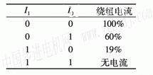
The uc3717 allows for step size control by selecting different combinations of I0 and I1. This enables various stepping modes, including full-step, half-step, and 1/4-step. The table below shows the relationship between I0, I1, and the corresponding winding current. In full-step mode, both windings are energized simultaneously, while in half-step mode, only one winding is energized at a time. The 1/4-step mode introduces an intermediate state between full and half steps, improving precision further.

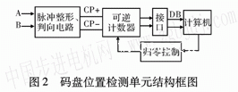
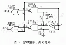
For position detection, an incremental photoelectric code disc is mounted on the motor shaft. As the motor rotates, the encoder emits pulses that are counted by a reversible counter. The computer reads this data to determine the actual movement distance. However, since the code wheel does not have a fixed zero point, a homing operation is required at the start of each cycle to reset the counter. The A and B output signals differ by 90 degrees, and their relative timing determines the direction of rotation. A pulse shaping and direction discrimination circuit, as shown in Figure 3, is used to detect forward and reverse movements accurately.

The three-axis linkage system, shown in Figure 4, uses a computer to control the motor via an I/O port. The stepping motor is connected to a ball screw through a coupling, enabling precise movement of the worktable in X, Y, and Z directions. A laser head is mounted on the system and controlled by the computer to carve the desired pattern onto the workpiece. The X, Y, and Z axis limit switches are mechanical switches that send signals to the CPU after being processed by a gate circuit on the interface board. These switches help establish the reference coordinate origin for the system.
The accuracy of the three-dimensional positioning system relies heavily on the precision of the detection device. To improve this, error models are developed based on the relationship between the system’s state and the sensor readings. During machining, the CNC system calculates real-time compensation values using these models and adjusts the measured data accordingly. This ensures high positioning accuracy across all axes, even under varying environmental conditions.
4. Conclusion: Laser engraving machines require precise and fast positioning along the X, Y, and Z axes. High-resolution hybrid stepper motors, combined with micro-step control and optical encoder technology, meet these demands effectively. The system is smooth, simple in design, and efficient in hardware-software integration, making it easy to maintain and operate.
Harvester Accessories,Parts For Combine Harvester,Part For Combine Harvester,Spiral For Combine Harvester
Changzhou Youeryou Trading Co., Ltd. , https://www.farmpartssupplier.com