The frequency domain phase codec system analyzes the relationship between the input optical pulse time period and the grating spectral resolution and code length in the formula, where α is a constant, α = 0.442; ω is the beam mode field radius; θd is the grating diffraction angle; F Is the code length; c is the speed of light in vacuum.
If it is assumed that ω = 10 mm, θd is π / 2, and the code lengths are 31, 127, and 512, respectively, the time period of the input optical pulse must not be greater than 1 ps, 0.24 ps, and 0.06 ps. According to [6], in the frequency domain phase codec system of the grating phase mask, when the number of simultaneous active users N is limited by the bandwidth of the light source and the spatial resolution, the number of users is  Where fin is the input optical pulse bandwidth; λ is the center wavelength of the optical pulse; Tg is the grating period; η is the correction factor.
Using phase encoding and decoding, regardless of the input "1" or "0", there is an optical signal output. Assuming that the probability of sending "1" or "0" is the same, the average optical power is accepted as  Where Ec is the energy of each chip light pulse; δ is the system energy error.
According to literature [7], when considering the code position error, it is assumed that the influence on the system signal-to-noise ratio is reflected in the increase in noise, and the system equivalent noise caused by the code position error is 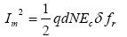 Shot noise and system thermal noise caused by optical pulses in the detector (subject to Gaussian distribution). Since shot noise and thermal noise are independent of each other [8], the total noise is
The signal-to-noise ratio of the system when considering shot noise and thermal noise is
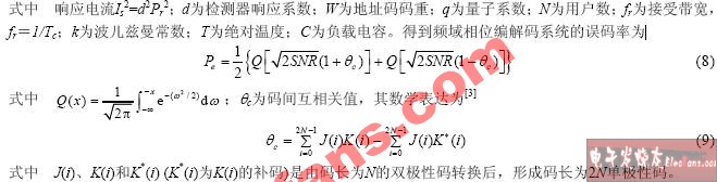
The signal-to-noise ratio of the system when considering the code position error is 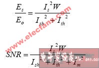
Simulation results and discussion The simulation was performed based on the analysis results of the frequency domain phase codec system. The simulation process assumes the use of bipolar Walsh codes, with code lengths of 31, 127, and 512, and a system working center wavelength of 1 550 nm. The results shown in Figures 3 to 6 are obtained.
Figure 3 plots the relationship between the number of activated users and the bit error rate under different received optical power conditions. The system assumes that each user's transmission rate is 622 Mb / s and the received optical power is 5, 10, 15 and 20 μW, respectively. It can be seen from Figure 3: When the bit error rate is the same as the number of active users, when the optical power increases, the value of the bit error rate of the system is also reduced. At 20 μW, the bit error rate is about 10−7, 10−11, 10−15, and 10−20. Using appropriate optical power can help improve the performance of the system. Figure 4 Different code position errors affect the performance of the system. When the code position error is 0.01, the code position error has little effect on the performance of the system. At this time, the bit error rate approaches the situation where the code position error is 0.
When the code position error is 0.2, the code position error has a greater impact on the performance of the system. For example, the signal-to-noise ratio is 15 dB, and the bit error rate has deteriorated by nearly an order of magnitude. It can be seen that the code position error needs to be considered when designing the LCM. It is important to improve the performance of the system.

Fig.3 The relationship between the bit error rate of different received optical power and the number of usersFig.4 The relationship between the bit error rate of different bit errors and the signal-to-noise ratio When the code length is 31, 127 and 512, the phase error is 0.2, BPSK is used During modulation, the relationship between bit error rate and signal-to-noise ratio is shown in Figure 5. It can be obtained from Figure 5: under the same phase error, when the code length is relatively large, the performance of the system is improved, for example, the signal-to-noise ratio is 15 dB, and the phase code length is 31, 127, and 512, respectively. 10−7, 10−10 and 10−13 respectively. When the code length is relatively small, the change curve of the bit error rate with the signal-to-noise ratio is relatively gentle, and on the contrary, the slope of the change curve is relatively large, indicating that the bit error rate is more affected by the code bit error than the short code word, so all systems are being considered The performance needs to adopt a compromise idea for code selection and LCM design. Figure 6 shows the effect of unipolar and bipolar codes on system performance. The solid line and the dotted line correspond to the relationship between the bit error rate and the signal-to-noise ratio of the bipolar code in ideal and non-ideal conditions. From equation (9), the cross-correlation of the bipolar code (such as Walsh) is small, as shown in Figure 6. As shown. The bit error rate and signal noise of the unipolar code are shown by long dashes. Because the correlation of the unipolar code is worse than that of the bipolar code, the figure shows that the bit error rate has greatly deteriorated under the same conditions. With a noise ratio of 15 dB, the bit error rate has deteriorated by nearly four orders of magnitude.
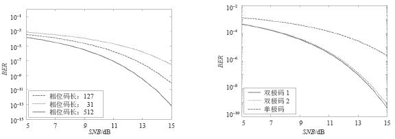
Figure 5 The relationship between the bit error rate and signal-to-noise ratio of different phase code lengths Figure 6 The relationship between the bit error rate and the signal-to-noise ratio of single bipolar codes
Based on the frequency domain phase encoding and decoding OCDMA system model, the mathematical expression of the effect of code position error on the B-OCDMA system is obtained. The effects of optical power, code error and codeword on the system are discussed through simulation. The results show that when the optical power is within the prescribed limit, the larger optical power greatly improves the system performance; when the code position error is about 0.20, the system performance deterioration is more obvious; when the codeword is larger, it is beneficial to improve the system performance ; In the system, when the code bit error is fixed, the choice of bipolar code is significantly better than the unipolar code. The research results of this paper have certain reference value in theory and practice.
Research on Performance of Frequency-domain Phase Optical Code Division Multiple Access System
Furniture Actuator
Furniture series are linear actuators designed specially for home application, like beds, sofa, lift chairs, massage armchair, lift recliners, etc. It has very low noise (quiet, <=48dB), strong load (max. 6,000N), and compact size (retracted length 163mm + stroke). And the whole motion system, including controller and Linear Actuator, is offered.
Furniture Actuator,Home Furniture Actuator,Furniture Linear Actuator,24V Furniture Actuator
TOMUU (DONGGUAN) ACTUATOR TECHNOLOGY CO., LTD. , http://www.tomuu.com