RFID systems are primarily composed of two key components: a reader and a transponder. The reader (Figure 1) functions as a data acquisition system that includes a coupling element designed to interact with the transponder. The transponder (Fig. 2), on the other hand, serves as a data carrier equipped with a coupling element made up of a microchip and an antenna coil [1].


Figure 1: Reader | Figure 2: Transponder
Figure 3 illustrates the working principle of the LC oscillator circuit used in passive RFID readers and transponders [2]. The reader contains an LC tank circuit consisting of an inductor L1 and a capacitor C1, which generates an alternating magnetic field at a frequency f0. In the transponder, the distributed capacitance C’ of the coil loop and an external tuning capacitor C form a parallel combination with the coil L2, creating an LC tank circuit with a resonant frequency f. When the transponder is placed within the magnetic field of the reader and the resonant frequency f matches the reader’s frequency f0, resonance occurs between the two circuits. This resonance causes a large current to flow through the reader's antenna coil, inducing a maximum voltage across the transponder’s coil. This voltage is then rectified by a diode to supply power to the microchip, enabling it to process information from the reader for reading or writing [3-4].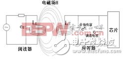
Figure 3: Working Principle of the LC Tank Circuit in Passive RFID Systems
The resonant frequency of the LC oscillation loop can be calculated using the Thomson formula (1):![]() (1)
(1)
![]() (2)
(2)
![]() (3)
(3)


Figure 4: Transponder Coil Printed with Conductive Ink | Figure 5: Transponder with 82 pF Capacitor
However, since the distributed capacitance C’ of the coil was not considered in the calculation, the 82 pF value actually represents the sum of both the distributed capacitance and the tuning capacitor. If the 82 pF capacitor is used directly, the total capacitance will increase, resulting in a lower resonant frequency than desired. Therefore, the tuning capacitor must be adjusted accordingly. To correct the value, the resonant frequency of the transponder needs to be repeatedly measured after each adjustment. This requires a specialized instrument capable of detecting the resonant frequency of the passive RFID tag. Since no such instrument is commonly available, the author designed a coupler to facilitate the detection process. Let’s take a closer look at this coupler. 3. Working Principle of the Coupler The core of the coupler consists of two sets of coils (coil 2 and coil 3) wound around a hollow cylinder. Each coil has a radius r and a number of turns N, and they are positioned parallel and coaxially with a center-to-center distance equal to the radius r, forming a Helmholtz coil [5-6], as shown in Figure 6.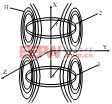
Figure 6: Schematic Diagram of Helmholtz Coil Structure
Taking the midpoint of the distance L as the origin O of the spatial coordinate system, the magnetic field distribution is illustrated in Figure 7.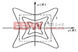
Figure 7: Magnetic Field Uniform Distribution Curve of Helmholtz Coil
The relative errors of the magnetic induction H at points along curves I, II, and III compared to the central point O are less than 1.0%, 0.1%, and 0.01%, respectively. This indicates that the magnetic field near the center point O is highly uniform. The closer the transponder is to the center, the more uniform the magnetic field becomes. Therefore, when testing the resonant frequency of a passive RFID transponder, it is placed at the center of the Helmholtz coil’s magnetic field to ensure uniform magnetic induction across the transponder’s plane.For Vivo Oca,Vivo Oca Sheet,Oca Sheet For Vivo Brand,Vivo X90 Oca Sheet Paper
Dongguan Jili Electronic Technology Co., Ltd. , https://www.jlglassoca.com