Introduction
This paper presents the design of a data recording device tailored for electric vehicle research. The system is integrated with the battery energy management system (BMS) to monitor and record critical battery parameters during real-world operation, such as voltage, current, and temperature. This device plays a vital role in analyzing battery performance and validating the BMS functionality, offering essential data support for theoretical studies on power batteries used in electric vehicles.
1. Overall System Design
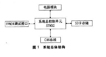
The design of the data recorder involves both hardware and software components. Software development includes data reception programming and data storage logic, while hardware design focuses on key elements like the main control chip selection, reset function implementation, power supply modules, real-time clock (RTC), communication interfaces, and SD card integration. The main control chip serves as the core of the system, integrating multiple functions to reduce external circuit complexity and improve design efficiency. Power modules are designed to meet various voltage requirements across the system, while the RTC ensures accurate time-stamping. An SD card is chosen for large-scale data storage. Given that most electric vehicles use CAN bus interfaces, the device communicates via CAN. The overall system architecture is illustrated in Figure 1.

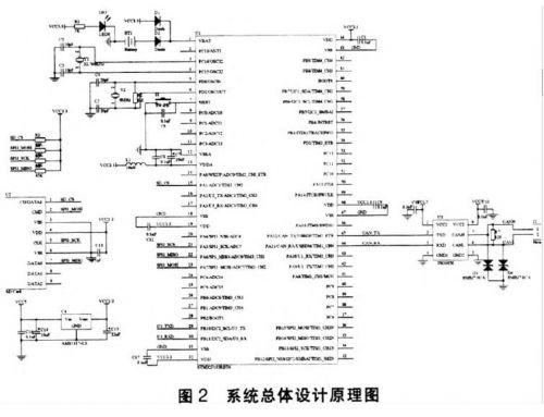
The schematic diagram of the hardware section is shown in Figure 2, illustrating the detailed layout of the system components.

2. Hardware Design
2.1 Main Control Chip Selection
The STM32F103RBT6 is selected as the main controller due to its high performance, low cost, and low power consumption. It is based on the 32-bit RISC core ARM Cortex-M3, operating at up to 72MHz. With a retail price around 12 yuan, it offers an excellent balance between cost and performance for this application.
2.2 Reset Function
The STM32F103RBT6 includes two built-in watchdogs: an independent watchdog and a window watchdog. These can detect and recover from software errors, triggering either a reset or an interrupt when a timeout occurs. The device also supports power-on and power-down resets, enhancing system reliability, timing accuracy, and flexibility. This internal reset mechanism ensures the system operates efficiently and meets all reset requirements.
2.3 Real-Time Clock (RTC)
The STM32F103RBT6 features an embedded RTC module, which acts as an independent timer. With proper software configuration, it provides calendar and timekeeping functions. The RTC counter can be adjusted to set the system's current time and date. The RTC and backup registers are located in the backup domain, ensuring their values remain intact after a system reset or wake-up from standby mode. When the main power (VDD) is disconnected, the VBAT pin supplies power to the RTC and backup registers, allowing continuous operation even when the main power is off. A CR1220 button cell is used as the backup battery to maintain RTC functionality and data integrity.
2.4 Power Module
The power module supplies the entire system with stable power. The STM32 requires a voltage range of 2.0–3.6V, and the RTC needs a separate backup power source. Here, a combination of VCC3.3V and a CR1220 battery is used. When the external power is removed, the CR1220 takes over to keep the RTC running. To provide a stable 3.3V supply for the microcontroller, an AVS17 voltage regulator from AMS is employed. This ensures reliable operation under varying power conditions.
 [1] [2]

Silicone Insulated Wire,Multi-Core Power Cord,Multi-Core Cable,High Temperature Wire
JIANGSU PENGSHEN HIGH TEMPERATURE WIRE CABLE CO., LTD. , https://www.pengshencable.com