Introduction
The digital input interface of a PLC is not complicated, but it plays a crucial role in ensuring reliable signal transmission. To enhance anti-interference capability, the input interface typically uses an optocoupler to isolate the external signal from the internal circuitry. This isolation ensures that the external input only needs to activate the LED inside the optocoupler, which then sends the signal to the receiving side through the optocoupler. This setup guarantees stable and safe signal transmission.
Currently, PLC digital input ports are generally divided into two types: single-ended common point (S/S) and double-ended input. In single-ended common point configurations, each manufacturer has its own standard for the common point—some use the positive side, while others use the negative. Japanese PLCs often use the positive common point, whereas European models tend to favor the negative. When supplying to international markets, manufacturers may adjust based on regional preferences. Some modern PLCs even offer S/S terminals that can be configured as either positive or negative, offering greater flexibility for users.
Understanding these differences is essential when selecting sensors or other external devices, as improper configuration can lead to system instability or failure during programming. This knowledge lays the foundation for successful integration and long-term reliability.
Types of Input Circuits
1. Classification of Input Types
PLC digital inputs are typically categorized as DC or AC based on their power supply type. They can also be classified as single-ended common point or double-ended based on the interface design. Single-ended common point inputs are further divided into sink (SINK) and source (SOURCE) types, depending on the polarity of the connection.

2. Explanation of Terms
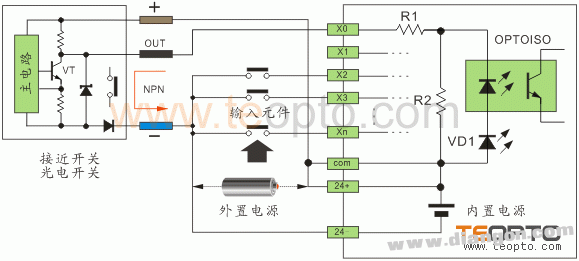
SINK (Sink Current): In this configuration, current flows from the input terminal to the power supply's negative terminal. The optocoupler is connected to the positive side of the power supply, and it works with NPN-type sensors.
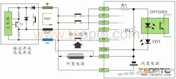
SOURCE (Source Current): Here, current flows from the power supply's positive terminal to the input terminal. The optocoupler is connected to the negative side, making it compatible with PNP-type sensors.
There are various ways to describe these terms:
- According to TI’s definition, sink current is the current drawn, while source current is the current supplied.
- Some refer to the polarity of the common point, distinguishing between positive and negative connections.
- SINK is associated with NPN sensors, while SOURCE is linked to PNP sensors.
- SINK is considered a negative logic connection, while SOURCE is a positive logic connection.
- SINK corresponds to active low signals, and SOURCE to active high signals.
These descriptions vary by region and manufacturer, so it's important to understand the context when working with different PLCs and sensors.
Proximity switches and photoelectric sensors often have three- or four-wire outputs, with NPN or PNP configurations. For non-detection states, NPN sensors output a high level, while PNP sensors output a low level. When a detection signal is present, the respective transistor turns on, switching the output to low or high accordingly.
It's important to note that some sensors are normally open, while others are normally closed. This affects how they interact with the PLC input. Users should carefully match sensor types with the correct PLC configuration to avoid issues during operation.
In some cases, users might connect a SINK input to a PNP sensor or a SOURCE input to an NPN sensor. While this may work in certain situations, it depends on the sensor's internal pull-up or pull-down resistors. Open-collector sensors, for example, require specific wiring to function properly. Not all combinations are universally compatible, so it's best to consult the manufacturer's documentation for detailed guidance.
3. Power Configuration Types
3.1 DC Input Circuit
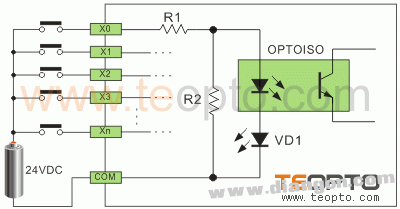
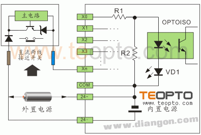
A DC input circuit requires the external component to be a passive dry contact or a DC switch. When the external component is activated, current flows through a resistor (R1), the optocoupler's LED, and the common terminal (COM). This activates the optocoupler, allowing the PLC to detect the signal. The DC power can come from the PLC itself or an external source. R2 helps prevent false triggering due to leakage currents from two-wire proximity switches.
3.2 AC Input Circuit
AC input circuits are similar to DC ones, but they include a bridge rectifier before the optocoupler to convert AC to DC. This makes them suitable for environments where electrical noise is high. If using a proximity switch, it can be directly replaced with an AC line switch without major changes to the wiring.

4. Port Types
4.1 Single-Ended Common Point (COM) Input Mode
This mode connects all input circuits to a common terminal (COM), reducing the number of required input terminals. For example, if there are N input points, you only need N+1 terminals. This structure is known as a "single-ended common point" input.
When wiring, one end of all components is connected to the common terminal, while the other ends are connected to individual input terminals (X0, X1, etc.). Depending on whether COM is connected to +24V or -24V, the input can be in SINK or SOURCE mode.
SINK mode is used with NPN sensors, and SOURCE mode with PNP sensors. Some PLCs provide an S/S terminal, allowing users to choose between SINK or SOURCE modes based on the application. This flexibility is especially useful in industrial settings where both Japanese and European PLCs are used.
4.1.1 SINK Input Mode
Connection: Internal COM → +24V, External Collinear → -24V.
Figure 3:

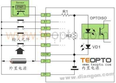
4.1.2 SOURCE Input Mode
Connection: Internal COM → -24V, External Collinear → +24V.
Figure 4:
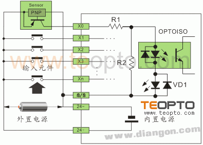
4.1.3 SINK/SOURCE Switchable Mode
The S/S terminal allows users to configure the input mode as either SINK or SOURCE, depending on the application. This provides greater flexibility compared to fixed COM terminals.
Figure 5:
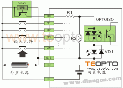
Figure 6:
4.2.4 When using multiple active sensors (such as Hall switches, proximity switches, or photoelectric sensors), the power consumption may exceed the built-in power supply of the PLC. In such cases, an external power supply should be used. It is important to ensure that the external power is not connected in parallel with the internal power supply. For SINK mode, the external power should be connected to the positive side; for SOURCE mode, to the negative side.
4.2.5 To determine whether the input is in SINK or SOURCE mode, simply short-circuit the Xn terminal with the negative or positive terminal, respectively. If the interface indicator lights up, the mode is confirmed. NPN sensors are used with SINK mode, and PNP sensors with SOURCE mode.
4.2.6 For 2-wire digital inputs, if the component is a passive contact, the wiring follows the same pattern as described above. For 2-wire proximity switches, the polarity must be correctly identified. Some of our LJK series proximity switches can be connected without polarity considerations, as specified in the product manual.
4.3 High-Speed Double-Ended Input Circuit
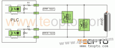
This type is used for high-speed counter inputs (HHSC) and operates at 5VDC. It uses a line-drive method to ensure high speed and noise immunity. If the operating frequency is low and noise is minimal, a 5VDC single-ended SINK or SOURCE connection can be used with a current-limiting resistor to adapt to 24VDC systems.
4.3.1 Two-Wire Line-Drive
Figure 7:

4.3.2 5VDC Single-Ended SINK/SOURCE
Figure 8:
4.3.3 24VDC Single-Ended SINK/SOURCE
Figure 9:
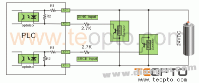
Note: A current-limiting resistor must be added in series with 24VDC sensors. R1 = 10Ω, R2 = 2KΩ. Without the resistor, the interface could be damaged. A resistor value of 2.7KΩ is recommended.
External Input Components
1. Passive Dry Contacts (Button Switches, Limit Switches, Reed Switches, Relay Contacts, etc.)
Passive dry contacts are simple to install and do not involve polarity or voltage drop issues. They are commonly used in basic applications and are shown in figures 3–6.
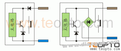
2. Active Two-Wire Sensors (Proximity Switches, Active Reed Switches)
Active two-wire proximity switches require a holding voltage of 3.5–5V after activation. Their static leakage current is typically less than 1mA, which is critical to prevent false triggering of the optocoupler. Our LJK series proximity switches are designed with low leakage current (0.35–0.5mA), making them compatible with most PLCs.
Some models have polarity protection, while others do not. For example, DC two-wire proximity switches with diode protection require attention to polarity, while those with bridge rectification do not. AC two-wire switches are polarity-independent.
Figure 10:
2.1 SINK Input Wiring
Figure 11:
2.2 SOURCE Input Wiring
Figure 12:

2.3 S/S Terminal Connection
Refer to Figures 5–6 and 11–12 for connection details.
3. Active Three-Wire Sensors (Inductive Proximity Switches, Capacitive Proximity Switches, Hall Proximity Switches, Photoelectric Switches)
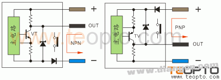
Three-wire DC sensors typically use NPN or PNP output configurations. Some models have four-wire outputs, with dual NPN or PNP configurations. These outputs are usually complementary, and some combine both NPN and PNP.
NPN Output: When a detection signal is present, the output current flows to the negative terminal, resulting in a low-level output.
PNP Output: When a detection signal is present, the output current flows from the positive terminal, resulting in a high-level output.
The emitter resistance provides short-circuit protection, while the collector resistance acts as a pull-up or pull-down resistor, ensuring proper signal levels. Open-collector outputs require external pull-up or pull-down resistors for proper operation.
Figure 13:
3.1 SINK Input Wiring
Figure 14:
3.2 SOURCE Input Wiring
Figure 15:
3.3 S/S Terminal Connection
Refer to Figures 5–6, 11–12, and 14–15 for connection methods.
Conclusion
PLC input interfaces and external sensor outputs vary significantly, making it essential to understand both before wiring. Proper configuration ensures accurate signal transmission, smooth operation, and long-term stability in real-world applications. This knowledge is crucial for successful PLC integration and programming.
A buzzer or beeper is an audio signalling device, which may be mechanical, electromechanical, or piezoelectric (piezo for short). Typical uses of buzzers and beeper include alarm devices, timers, and confirmation of user input such as a mouse click or keystroke.
Piezo Buzzer,Dc Electro Magnetic Buzzer,Buzzer Acoustic Components,Piezo Buzzer For Thermometer
Jiangsu Huawha Electronices Co.,Ltd , https://www.hnbuzzer.com