Coordinate system: A position indicator system that is performed on a robot or space to determine the position and posture of the robot.
The coordinate system contains:1. Base Coordinate System
2, the Earth Coordinate System (World Coordinate System)
3. Tool Coordinate System
4, the workpiece coordinate system (Work Object Coordinate System)
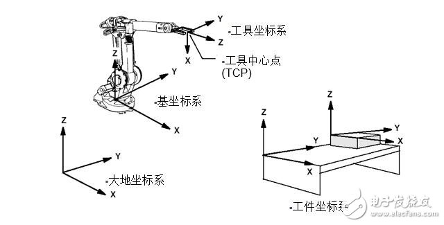 1, the tool coordinate system
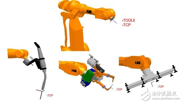
 The robot tool coordinate system consists of the tool center point TCP and coordinate orientation.
TCP is required when the robot is linked.
1) Reorient Relocation motion (attitude motion) The robot's TCP position is unchanged, and the robot tool rotates along the coordinate axis to change the attitude.
2) The linear linear motion robot tool has the same attitude, and the robot TCP moves along the coordinate axis.
The robot program supports multiple TCPs and can be transformed according to the current working state.
After the robot tool is replaced and the TCP is redefined, it can be run without changing the program.
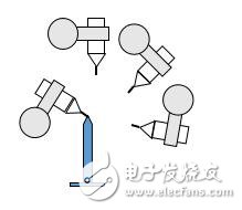
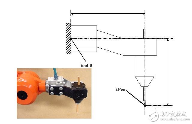 1.1. Method of defining the tool coordinate system:
 1. N(N>=4) point method/TCP method-robot TCP collides with a fixed point through N different poses to obtain multiple sets of solutions, and calculates the corresponding position of the current TCP and the robot wrist center point (tool0). The coordinate system direction is the same as tool0.
2, TCP & Z method - on the basis of the N point method, the Z point and the fixed point connection are the coordinate system Z direction.
3. TCP&X, Z method - On the basis of the N point method, the X point and the fixed point connection are the coordinate system X direction, and the Z point and the fixed point connection are the coordinate system Z direction.
 2. Workpiece coordinate system
 The robot workpiece coordinate system consists of the workpiece origin and coordinate orientation.
The robot program supports multiple Wobjs and can be transformed according to the current working state.
The external fixture is replaced. After redefining Wobj, you can run it without changing the program.
By redefining Wobj, one program can be easily completed for multiple robots.
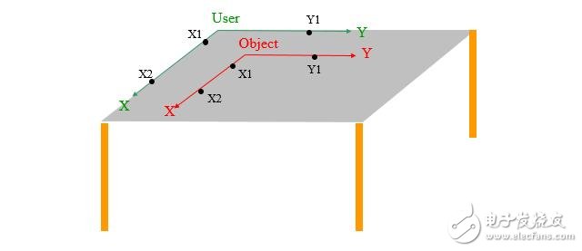
2.1. Method of defining the workpiece coordinate system:The three-point method - the point X1 and the point X2 are connected to form the X axis, and the vertical line from the point Y1 to the X axis is the Y axis.
DC Permanent Magnet Gear Motor
Dc Motor,24V Dc Gear Motor,Electric Gear Motor,Dc Permanent Magnet Gear Motor
NingBo BeiLun HengFeng Electromotor Manufacture Co.,Ltd. , https://www.hengfengmotor.com