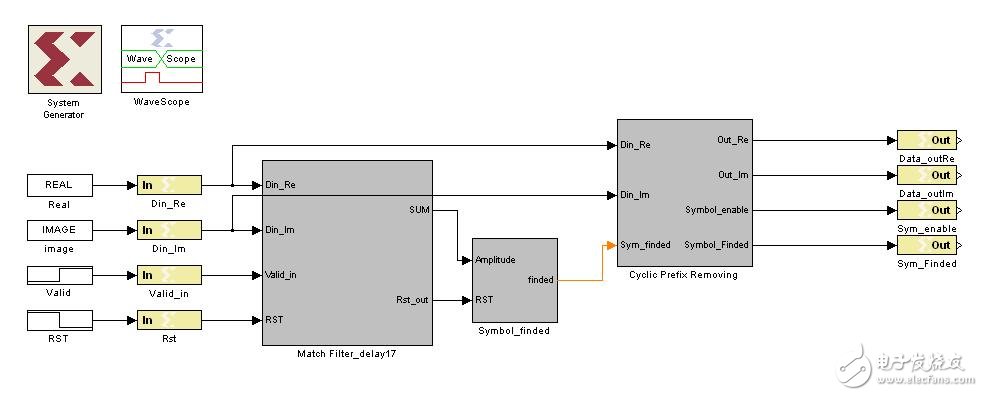
Last time we mentioned that we can use the locally stored training sequence to perform matched filtering (correlation) with the received sequence to search for the exact starting position of the OFDM symbol. The block diagram of the entire module is as follows:
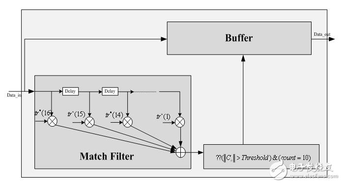
(1) The first part of the block diagram is the matched filter (correlator). If we directly call the complex multiplier, we need 16 complex multipliers. For such a large resource requirement, we must try to simplify. (Note: This is not the case we encountered earlier. The previous is to calculate the autocorrelation of the accepted sequence. It can be implemented with only one complex multiplier, but here, the accepted sequence is related to the locally stored value. Must have 16 complex multipliers)
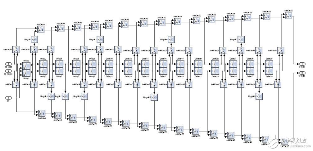
In practice, considering the resources of saving chips, the locally stored sequence can be quantized (positive (including 0) is quantized to 1 and negative quantized to -1). Of course, the received sequence can be quantized, but this will A little more complicated. That is to say, we approximate the locally stored sequence to 1+j, 1-j, -1-j, -1+j for the sake of simplicity of calculation (this is allowed because of the good autocorrelation of the training sequence). of). Therefore, it is possible to use the addition and subtraction method instead of the complex multiplication to achieve the purpose of saving chip area.
In order to theoretically compare the results after the approximation, I use the quantized local sequence to cross-correlate with the received sequence (that is, match the filter) as shown below, and the noise is superimposed on the received signal.
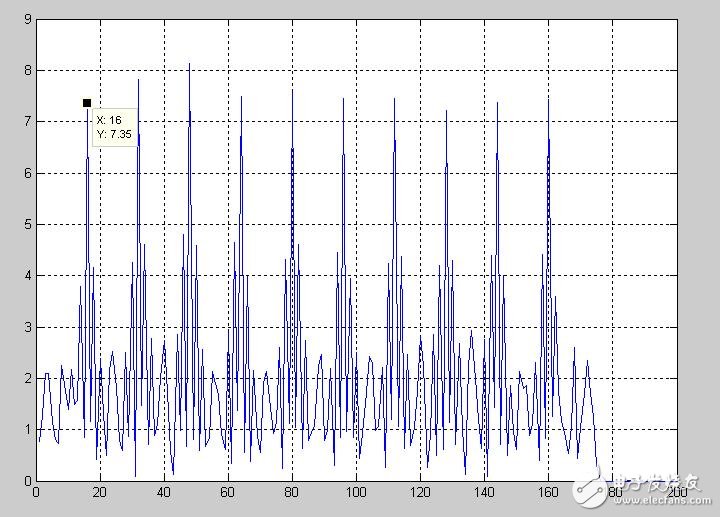
From the theoretical results, we make the above approximation feasible. In this way, the original complex multiplier can be omitted. It is very convenient to add and subtract the real part and the imaginary part of the data at all levels. It is very convenient. Of course, it is very annoying when connecting the modules, so you must be very careful.
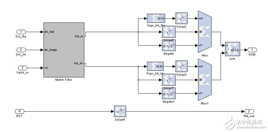
(2) After the data passes through the matched filter, we need to calculate the amplitude of the result. Of course, we will not seek the square sum of the real part and the imaginary part. On the one hand, such resource consumption is considerable, on the other hand, completely no need. We only need to ask for the sum of the absolute values ​​of the real and imaginary parts, and adjust the threshold appropriately. Similar to the way I implemented packet detection in the first article, I won't go into details. As shown below:
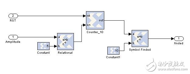
(3) Symbol search module: This unit is responsible for detecting whether the calculated amplitude is greater than the set threshold and counting the number of peak occurrences. When the number of times is the number of segments of the short training sequence (10), this is the long training. The sequence loop prefix starts exactly where. Regarding the setting of the threshold value, it is necessary to carry out theoretical simulation first, and consider the influence of the actual channel, and adjust it flexibly. Generally, it is necessary to repeatedly debug. (In fact, I think this kind of setting absolute threshold is not good, because the actual channel environment is complex, it is impossible to set an absolute threshold for all environments, you can consider setting the relative threshold). As shown below:
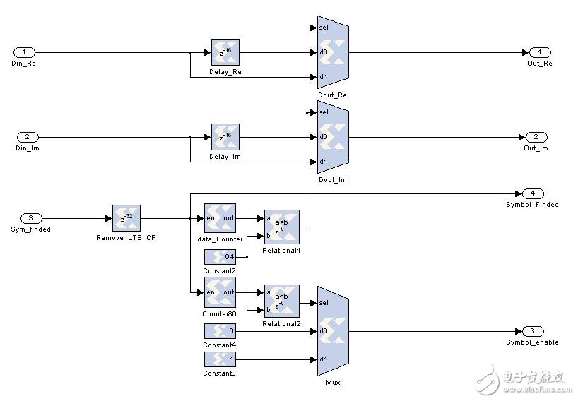
(4) The cyclic prefix removal unit considers that the exact position of the symbol has been found, so the cyclic prefix portion of the long training sequence symbol and the data symbol can be removed, and the signal Symbol_enable is used to indicate whether the data is valid (the data is valid when 1), and the effective time is The length of the data in a symbol, the duration of Symbol_enable is low for 16.
Because the standard specifies that the cyclic prefixes of the two long training sequences are consecutive, that is, the first 32 data we discard, we only need to delay the previous module's Symbol_finded by 32 units.
The subsequent two long training sequences, 64X2, are guaranteed to be the same as the structure of the following data. We do the following:
First, 64 samples are output (the first long training sequence), and all subsequent samples are delayed by 16 units of time. At the same time, a counter of the modulo 80 is used to output a pulse having a duty ratio of 4/5, which is used to indicate whether or not the data is a valid symbol at this time.
(5) Finally, attach the top file of this design and the simulation waveform:
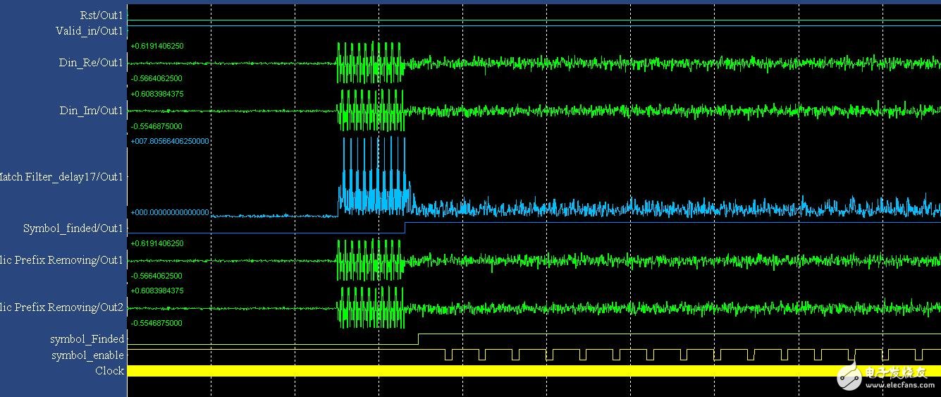
In the simulation waveform, we superimpose the signal with 15db noise. The basic functions we have realized are the output signals for data (real part, imaginary part) and Symbol_Finded (indicative symbol exact starting position) and Symbol_enable (indicating valid data). The subsequent unit is the FFT unit, so this unit is a key part of system synchronization. Returning to SysGen, we can see that as long as the structure is very clear, from the basic algorithm to the hardware implementation, the Xilinx DSP tool is very convenient and very visual. Compared with the code method, the integration speed is greatly improved.
Platform Type Scanner
JUMP WELL brand platform image scanner. The use of environmentally friendly fill light, eye protection mode, support a whole day of work effortlessly, imaging technology, megapixels, so that every scan can be easily and quickly, can be widely used in supermarket platforms, catering industry, logistics industry, etc. It can easily deal with the super-large warehousing products. The appearance is simple and beautiful, and the bottom has a non-slip design, so that the scanning instrument is not easily damaged by slipping.
Platform Type Scanner,Supermarket Cashier Scanner,Front Desk Cashier Scanner,Catering Platform Cashier Scanner
Shenzhen Geyi Technology Co., Ltd. , https://www.gy-printer.cn