In the realm of high-speed counting, the PRV command plays a crucial role in reading input pulse frequency and measuring the frequency of a high-speed counter. This measured frequency can be output in Hz or as an 8-bit hexadecimal value, and it is specifically designed for use with high-speed counter 0. Importantly, even while performing frequency measurement, the high-speed counter's functionality, such as comparison operations and pulse output, remains unaffected.
To implement high-speed counter frequency measurement, follow these steps:
1. **High-Speed Counter Usage Setup**: In the PLC system settings, ensure that [High-Speed Counter 0 Use/Non-Use] is set to "Use".
2. **Counter Selection**: Configure [High-Speed Counter] / [Pulse Input Method] within the PLC system settings.
3. **Value Range Mode Selection**: Set [High-Speed Counter 0] / [Value Range Mode]. If using the ring mode, adjust [High-Speed Counter 0] / [Ring Counter Maximum].
4. **Reset Mode Configuration**: Choose the appropriate reset mode for the current value of the high-speed counter under [High-Speed Counter 0] / [Reset Mode].
5. **Execution of PRV Instruction**: The operand N should correspond to the high-speed counter input (e.g., #0010), operand C is used for frequency reading (#0003), and operand D is the frequency storage channel.
The specifications of the high-speed counter during frequency measurement are detailed in the table below.

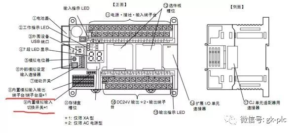
Moving on to analog knowledge, it's essential to understand that analog programming often involves hardware configurations beyond just software calculations. For instance, you must select between current and voltage signals, choose the resolution (such as 6000 or 12000), and determine the channel and range (like 4-20mA or 0-5V). These settings are typically done through DIP switches located on the device.
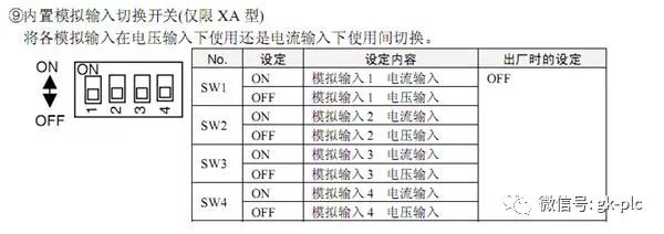
Once the wiring is correctly connected, you need to configure whether the analog signal is set to current input or voltage input. The four DIP switches shown above allow for this configuration.
After setting up the hardware, it's time to move to the software interface. Here, you'll need to specify the selected channel, resolution, and range. Proper configuration in both hardware and software is vital to ensure accurate analog calculations and engineering unit conversions.
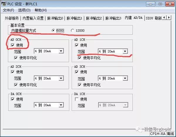
Without correct settings, any analog processing will fail, and the program may not function as intended.
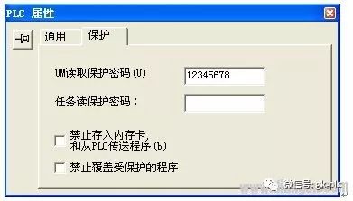
Lastly, setting a password for encryption is a critical step in protecting your PLC program. In the CX-P programming environment, right-click on "New PLC," select "Properties," then go to "Protect." Enter an 8-digit password in the "UM Read Protection Password" field, as shown below.
After downloading the program to the PLC, navigate to the "PLC" dropdown menu and select "Protect" > "Set Password."
For releasing the password:
Once the CX-P software is online with the PLC, go to "PLC" > "Protect" > "Release Password" and enter the password.
**Note**: To prevent other users from overwriting your protected program, check the "Prohibit Overwriting Protected Programs" option in the properties. If you want to overwrite the PLC program later, you must first release the password.
Jinan Guohua Green Power Equipment Co.,Ltd. , https://www.guohuagenerator.com