Let me start by explaining the origin of this project. Initially, I built the system using an ARDUINO MEGA2560 board along with various modules, and the code was written directly in the ARDUINO IDE. However, this kind of patchwork setup wasn't very reliable—especially when it came to power supply issues. The previous ARDUINO board's power supply got damaged. After checking the schematic, I realized that when both the computer's USB power and a 12V power source were connected, the 5V from the USB and 12V were connected in parallel. This created a large current flow, which is actually risky. I did some research online and found that connecting two power supplies of the same voltage in parallel can lead to uneven current distribution due to differences in internal resistance, which might even damage the power sources. That’s why I decided to redesign the circuit based on open-source schematics, improve the power supply design, and integrate all components onto a single PCB. I also updated the firmware accordingly and programmed the microcontroller.
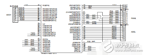
Now, I’d like to explain the relationship between AVR and ARDUINO. ARDUINO is an open-source platform based on ATMEL's AVR microcontrollers. It also includes its own development environment, the ARDUINO IDE. So how exactly are ARDUINO boards built around AVR microcontrollers? For example, the ARDUINO MEGA2560 uses the AT MEGA2560 as its main controller. ARDUINO maps some of the general-purpose I/O pins of the AVR MCU and assigns them new names. For instance, PD0 becomes digital pin 21 on the MEGA2560, while PF0 corresponds to ADC0 on the analog input A0. Each version of the ARDUINO board comes pre-configured with specific settings for the AVR MCU. These settings can be found in the boards.txt file located in the hardware/arduino folder within the ARDUINO installation directory. This file contains information such as fuse bit settings, serial baud rate, bootloader location, and more. When you select a board in the ARDUINO IDE, it automatically applies the parameters defined in this file.
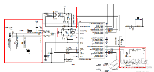
After discussing the I/O ports, let's move on to the programming method of ARDUINO. The AVR microcontroller supports several programming methods, including ISP, JTAG emulation, and high-voltage parallel programming. Early versions of ARDUINO used the CH340G chip for USB-to-serial communication. Later, starting from a certain version, the AT MEGA8 and 16 were used to implement USB-to-serial functionality. Here is the schematic diagram of the download module for the ARDUINO MEGA2560:
The BOOTLOADER is a small program stored in a dedicated area of the FLASH memory. It runs before the main application and is commonly used for initialization tasks. In the case of ARDUINO, it enables serial port programming. The exact steps will be explained later.
Now, let me talk about my development process.
I. Using PROGISP to Download Programs Written in ARDUINO IDE
Since my micro USB port wasn’t soldered, and I didn’t want to waste the already soldered board, I used PROGISP to upload the program I wrote in the ARDUINO IDE. Normally, the ARDUINO board is programmed via the USB port, but to use PROGISP, I needed to compile the hex file first. To export the hex file from the ARDUINO IDE, follow these steps:
Open the ARDUINO IDE, go to File > Preferences, click the path of the C drive, and open preferences.txt with Notepad.

Make sure to close the ARDUINO IDE (this is crucial!).
Once preferences.txt is opened in Notepad, set the path where the hex file will be saved. Add the line build.path=D:\arduino\MyHexDir to the end of the file. Choose your own directory, then save and close the file.
If everything is done correctly, the compiled HEX file should appear in the specified directory. If not, it may be because the ARDUINO IDE was still open when editing the file. In that case, restart the editor and check if the line was added properly.
Next, I need to configure the AVR microcontroller. This was my first time working with an AVR, so I had a lot to learn. I initially thought I could just use the CH340G for programming, but that turned out not to be the case. One of the most important aspects of the AVR is the fuse settings. These determine the clock selection, system clock division, startup address, and other critical configurations. By default, the AVR uses the internal RC oscillator. Since I used an external 16MHz crystal on my board, I had to adjust the fuse bits to select the external clock source. This required programming via ISP, so I added an ISP header to the second version of my PCB and purchased two USB ISP programmers online. Unfortunately, the computer didn’t recognize the devices, and they weren’t showing up in the Device Manager. Fortunately, the seller provided a driver-free burning software, which I used to successfully program the fuses.
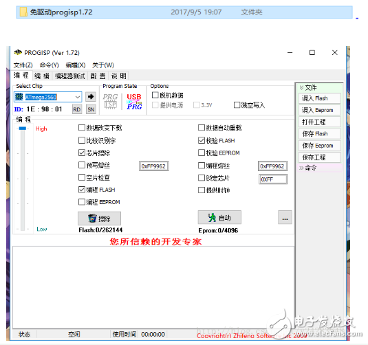
This software has a wizard mode that simplifies the fuse configuration, making it much easier for beginners. You don’t need to understand every detail of the fuse settings, which makes the process much smoother. With this tool, I was able to successfully modify the fuse settings and burn the program (remember to always select the correct microcontroller model first). Of course, there were some challenges along the way. For example, I accidentally set the "system clock divide by 8" option, which caused the actual clock speed to be only one-eighth of the crystal frequency. Also, I chose to move the reset vector to the boot area, which prevented the microcontroller from running my code. The main issue was the clock configuration. Let me clarify: "RC oscillator" refers to a clock circuit made with resistors and capacitors, while "external clock" means using an active crystal oscillator. The passive crystals we usually see are called "external low-frequency crystal oscillators." I was confused about what "external full-scale crystal oscillator" meant. I looked up the corresponding fuse bit values and eventually understood the difference. In short, the key is to choose the right clock source for your microcontroller.
Elevator Advertising Projector
Elevator projector,projector Elevator,elevator projection,elevator projector advertising,Smart elevator projector,elevator advertising projector
Guangdong Elieken Electronic Technology Co.,Ltd. , https://www.elieken.com