Those familiar with microelectronic process equipment know that RFGENERATER is an indispensable device for semiconductor processes and is mainly used in plasma dry etching equipment. The principle is that the etching gas (mainly F-based and C1-based gas) is introduced into the reaction chamber through the gas flow control system, and a glow discharge is generated under the action of a high-frequency electric field (frequency usually 13.56 MHz), a negative gas molecule or The atoms are ionized to form a plasma. A plasma is a non-aggregating system that contains enough positive and negative charge numbers to be nearly equal to charged particles. The RF source is the core device that generates high-frequency electric fields.
At present, the price of a radio source used in a new dry etching equipment is about 10,000 US dollars, and the cost of repairing an RF source is generally more than 10,000 yuan, which shows that the cost is quite expensive. In line with the principle of saving wood, the unit performs independent maintenance on the RF source that has failed during use. In order to verify whether the RF source can meet the requirements of use after maintenance, according to its use principle and the input and output of its control signal, the RF source remote control transceiver signal simulator is developed spontaneously. After the successful development of the equipment, the situation that the previous RF source must be debugged after maintenance is changed, thereby realizing offline debugging, achieving the purpose of saving time and labor and saving cost.
2 design plan
In order to achieve the purpose of offline debugging of the RF source, the main purpose is to simulate the original device host PRMOTE control function, including the following points:
(1) A determination as to whether the RF source is turned on;
(2) Determination of the interlock function (interlock);
(3) setting the output power of the RF source;
(4) Measurement of the forward power of the RF source;
(5) Measurement of the reverse power of the RF source.
Firstly, the panel is designed. Referring to the main structure of the RF source panel, combined with the actual functional requirements, the panel appearance is shown in Figure 1.
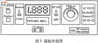
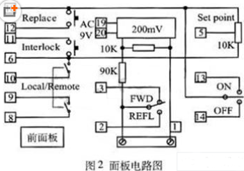
As can be seen from the panel design, the panel function keys include RF power switch key, interlock function (interlock) test button, RF source output power setting knob, RF source forward/reverse power measurement switch, and reset button. There are also displays and indicators on it. Its circuit diagram is shown in Figure 2.
Applications:
The Grounding Transformer is a kind of auxiliary transformer that used to offer an earth point for the Delta-Star system. They are typically used for providing a path to ground for unbalanced load current and for fault currents on system where a suitable ground is otherwise not available.
Design:
The grounding transformers are generally designed with one of the two configurations: Zig-Zag (Zn) with or without an auxiliary winding or a Wye (Ynd) with a delta connected secondary. The Zig-Zag connection is preferred as it is more cost effective and have smaller size than the Delta-Wye unit. For more safety, neutral earthing resistors (NER) are often used in conjunction with the grounding transformer to limit neutral ground fault current magnitude. The rated voltage of the NER should be equal to the line to ground voltage of the grounding transformer. The current rating and duration should match the grounding transformer
Why SCOTECH
Long history- Focus on transformer manufacturing since 1934.
Technical support – 134 engineers stand by for you 24/7.
Manufacturing-advanced production and testing equipment, strict QA system.
Perfect service-The complete customer service package (from quotation to energization)
Grounding Transformer
Grounding Transformer,Neutral Grounding Transformer,Neutral Earthing Transformer,Neutral Grounding Transformer For Generator
Jiangshan Scotech Electrical Co.,Ltd , https://www.scotech.com