When college students study electronic courses such as Electronic Circuits and Signal Processing, they often only grasp the theoretical aspects of signal characteristics. However, they lack the practical experience to observe or analyze real signals. The amplitude-frequency and phase-frequency characteristics are fundamental properties of a signal. To bridge this gap, a frequency characteristic tester based on a single-chip microcontroller (MCU) and Field-Programmable Gate Array (FPGA) has been designed. This system enables students to visually test and understand the frequency characteristics of signals in a hands-on manner.
DesignThe system employs a sweep test method. Let the frequency response be H(jω). When the system is linear with real coefficients, the steady-state output of a time-invariant system under the excitation of a sinusoidal signal x(n)=Acos(ω₀n+ψ) is y(n). Using trigonometric identities, the input x(n) can be expressed as the sum of two complex exponential functions:
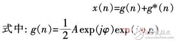
If the input is exp(jω₀n), the steady-state output of the linear time-invariant system is H(exp(jω₀n))exp(jω₀n). Based on the linearity of the system, the response v(n) to the input g(n) is:
Similarly, the output for the input g*(n) is v*(n), which is the complex conjugate of v(n). Thus, the output y(n) becomes:
From the above, when the system is excited by a sinusoidal signal, the output reaches a steady state and is a sine wave with the same frequency as the input. The ratio of the output amplitude to the input amplitude represents the amplitude-frequency characteristic, while the phase difference corresponds to the phase-frequency characteristic. Therefore, the frequency characteristics are measured using a frequency sweep method.
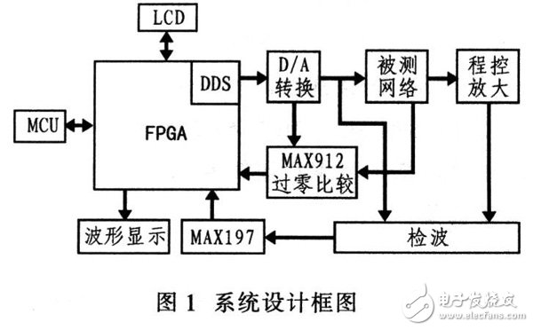
The system uses a single-chip microcontroller and FPGA as the core. A sine wave generated by Direct Digital Synthesis (DDS) is used as the sweep signal. It is fed into the network under test, and a peak detection circuit measures both the input and output signals at each frequency point. The amplitude-frequency characteristics are determined from the proportional relationship between the input and output signals. Meanwhile, the FPGA counts the number of pulses representing the phase difference between the input and output signals, and sends this data to the microcontroller to calculate the phase angle. These results are stored in the FPGA’s RAM and displayed on an oscilloscope along with a sawtooth wave. An LCD also displays the start, end, and step values of the frequency sweep. For fixed-point measurements, the LCD shows the amplitude and phase of a specific frequency point. The system block diagram is shown in Figure 1.
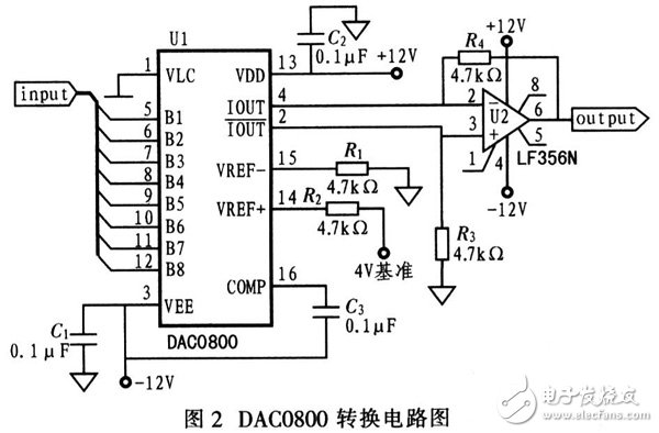
The DDS signal is generated inside the FPGA and converted into a sine wave using a D/A converter. The DAC0800 is used for this purpose. It features 8-bit resolution, a 100 ns output current settling time, and an operating voltage range of ±4.5 to ±18 V. This allows the generation of 256 samples, which meets the system's accuracy requirements. The maximum output frequency is 200 kHz, and the 100 ns settling time is sufficient for the application. Since the DAC0800 outputs current rather than voltage, an operational amplifier is used for I-V conversion. The conversion circuit is shown in Figure 2. Additionally, a low-pass filter is required to smooth the output signal and reduce harmonic distortion.
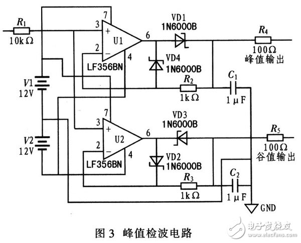
The peak detection circuit works by charging a capacitor during the positive half-cycle of the input voltage. The capacitor is chosen so that its discharge rate is faster than the charging rate, allowing it to hold the peak voltage. This peak voltage is then output through an emitter follower made of an operational amplifier, which provides high impedance isolation. The LF356 operational amplifier is used due to its low input offset voltage, low input offset current, and high input impedance, making it ideal for isolating different stages of the circuit. The peak detection circuit is shown in Figure 3.
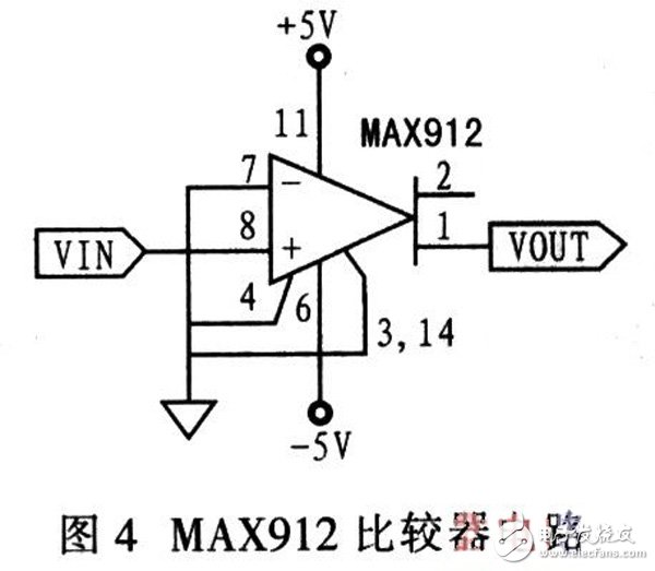
The input and output signals are amplified by an op-amp and fed into a zero-crossing comparator, which generates a square wave that reflects the phase difference between the two signals. This square wave is then sent to the FPGA for phase difference counting. The MAX912, a high-speed, low-power comparator from Maxim, is used for this purpose. It offers fast propagation speed (typically 10 ns), low power consumption (6 mA per comparator), and independent latch enable functionality. Since the FPGA detects the falling edge for phase measurement, a high-speed zero-crossing comparator is essential to produce sharp edges. The circuit is shown in Figure 4.
What can the Screen Protector Cutting Machine do?
This is a customized universal cutting machine that can cut Screen Protectors and Back Filmns suitable for mobile phones,
iPads, smart watches, macbook etc.
One Cutting Machine can cut all types of Mobile Phone Screen Protectors. The cutting accuracy is 0.1mm. It can cut more
than 22000+ mobile phone models and styles, and any model can be cut. 0 inventory, no need to worry about large
inventory, to meet the large needs of customers.
In the Mobile Phone Screen Protector industry, in order to meet the requirements of consumers in the traditional mobile phone film business model, many practitioners will prepare a large number of Mobile Phone Screen Protectors for popular mobile phones. However, the alternate iteration of new and old mobile phone models is too fast, and the cycle is greatly shortened, resulting in many screen protectors that have not been able to be sold in time, and can only be disposed of by themselves. and profit margins will suffer as a result. It is against this background that the Screen Protector Cutting Machine was born, and its appearance can improve the operating status of the Screen Protector industry.
Protective Film Cutting Machine,Back Sticker Cutting Machine,Phone Sticker Cutting Machine,Flim Cutting Machine
Shenzhen TUOLI Electronic Technology Co., Ltd. , https://www.tlhydrogelprotector.com